Frequency Detector Library for Arduino and ATtinys
Available as Arduino library "FrequencyDetector"
Version 2.0.1 - work in progress

![]()
![]()
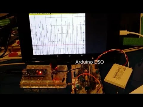
Detects frequency from 38 Hz to 9612 Hz and works even on an ATTiny85 with 1 MHz up to 4806 Hz. The input signal can be plotted to the Arduino Serial Plotter resulting in a simple Oscilloscope to test the internal signal.
YouTube video of whistle switch example in action.

Internal operation
This library analyzes a (microphone) signal and outputs the detected frequency. It simply counts zero crossings and it does not use FFT.
The ADC sample data is not stored in RAM, only the period lengths (between triggers) are stored in the PeriodLength[] array,
which is a byte array and has the size of NUMBER_OF_SAMPLES / 8.
It is like in the Arduino Simple Audio Frequency Meter but includes additional noise check.
The timer 0 interrupt, which counts the milliseconds, is disabled during reading and enabled afterwards!
The value of millis() is adjusted after reading.
The alternative to disabling the interrupt is getting partially invalid results!
There are 3 detection ranges available:
FREQUENCY_RANGE_HIGH-> 13 µs/sample -> 300 to 9612 Hz with 1024 samples and 600 to 9612 Hz with 512 samples.FREQUENCY_RANGE_DEFAULT-> 52 µs/sample -> 75 to 2403 Hz with 1024 samples and 150 to 2403 Hz with 512 samples.FREQUENCY_RANGE_LOW-> 104 µs/sample -> 38 to 1202 Hz with 1024 samples and 75 to 1202 Hz with 512 samples.
readSignal() is the ADC read routine, which reads 1024 samples (512 for ATtinies) and computes the following values:
- Frequency of signal
uint16_t FrequencyRaw - Amplitude = (MaxValue - MinValue)
uint16_t SignalDelta - Average = (SumOfSampleValues / NumberOfSamples)
uint16_t AverageLevel - The length of each period (between 2 trigger conditions) in the
PeriodLength[]array.
doEqualDistributionPlausi() checks if the signal in the PeriodLength[] array is valid / not noisy.
It checks if at maximum 1/8 of the periods are greater than 1.5 or less than 0.75 of the average period.
If not, the value of FrequencyRaw is overwritten with the error code SIGNAL_DISTRIBUTION_PLAUSI_FAILED.
computeDirectAndFilteredMatch() waits for n matches within a given frequency range (FrequencyMatchLow - FrequencyMatchHigh)
and also low pass filters the result for smooth transitions between the 3 match states (lower, match, greater). It computes the following values:
- Low pass filtered frequency of signal
uint16_t FrequencyFiltered; - Match result
MatchStateEnum FrequencyMatchDirect; - Low pass filtered match result
MatchStateEnum FrequencyMatchFiltered
By enabling PRINT_INPUT_SIGNAL_TO_PLOTTER in FrequencyDetector.h, it can be used as a simple oscilloscope using the Arduino Serial Plotter.

Dependencies
The ATtinySerialOut library is required for print functions on ATtinies.
SimpleFrequencyDetector example
This example reads analog signal e.g. from MAX9814 Module at A1 and computes the frequency.
If frequency is in the range of 1400 to 1700 Hz, the Arduino built in LED will light up.
It prints the detected frequency as well as plausibility errors.
For frequency below 500 Hz it might be good to change FREQUENCY_RANGE_DEFAULT to FREQUENCY_RANGE_LOW.
SimpleFrequencyDetector on breadboard with MAX9814 Module
 YouTube Demonstration of SimpleFrequencyDetector with MAX9812 Module
WhistleSwitch example
The WhistleSwitch example analyzes a microphone signal (I use a MAX9814 module from Adafruit) and toggles an output pin, if the main frequency is for a specified duration in a specified range.
It works as a frequency detector for a whistle pitch which operates a mains relay. By using different pitches it is possible to control multiple relays in a single room.
If the pitch is lower than the specified frequency, the feedback LED blinks slowly, if the pitch is higher it blinks fast.
If the (low pass filtered) match from the FrequencyDetector library holds for MATCH_TO_LONG_MILLIS (1 second) after switching output,
the output switches again, to go back to the former state.
This can be useful if a machine generated signal (e.g. from a vacuum cleaner) matches the range.
This example is mainly created to run on an ATtiny85 at 1 MHz, but will work also on a plain Arduino.
Arduino Plotter output of WhistleSwitch in action
Above you see the FrequencyRaw I whistled with all the dropouts and the FrequencyFiltered without dropouts but with a slight delay if the FrequencyRaw changes.
The WhistleSwitch example uses the FrequencyMatchFiltered value, to decide if a match happens. At 80 and 140 you see 2 short and at 300 you see a long valid match.

PREDEFINED RANGES
After power up or reset, the feedback LED echoes the range number. Range number 10 indicates an individual range, programmed by advanced selecting. The timeout state is signaled by short LED pulses after the range number feedback (no short pulse -> no timeout enabled).
the following pitch ranges are predefined for easy selection:
-
1700 - 2050 Hz -> 350 Hz A6-C6
-
1500 - 1680 Hz -> 180 Hz FS6-GS6
-
1300 - 1480 Hz -> 180 Hz E6-FS6
-
1150 - 1280 Hz -> 130 Hz D6-DS6
-
1000 - 1130 Hz -> 130 Hz C6-CS6
-
900 - 990 Hz -> 90 Hz A5-B5
-
1550 - 1900 Hz -> 350 Hz G6-AS6
-
1250 - 1530 Hz -> 380 Hz DS6-G6
-
1000 - 1230 Hz -> 230 Hz C6-DS6
-
Dummy range, if chosen, disables "relay on" timeout handling.
-
Dummy range, if chosen, sets "relay on" timeout to 2 hours.
-
Dummy range, if chosen, sets "relay on" timeout to 4 hours.
-
Dummy range, if chosen, sets "relay on" timeout to 8 hours.
SELECTING the RANGE
Selecting is started by a long press of the button.
After BUTTON_PUSH_ENTER_PROGRAM_SIMPLE_MILLIS (1.5 seconds), the feedback LED blinks once for signaling simple programming mode.
After BUTTON_PUSH_ENTER_PROGRAM_ADVANCED_MILLIS (4 seconds), the feedback LED blinks twice for signaling advanced programming mode.
After releasing the button, the selected programming mode is entered.
SIMPLE PROGRAMMING MODE
Press the button once for range 1, twice for range 2 etc. Each button press is echoed by the feedback LED.
Waiting for PROGRAM_MODE_SIMPLE_END_DETECT_MILLIS (1.5 seconds) ends the programming mode
and the feedback LED echoes the number of button presses recognized.
The duration of signal match to toggle the relay is fixed at MATCH_MILLIS_NEEDED_DEFAULT (1.2 seconds).
ADVANCED PROGRAMMING MODE
Whistle the pitch you want to detect, then press the button again. While you press the button, the pitch range is measured. i.e. the minimum and maximum of the pitch you are whistling is stored.
If you press the button again before the PROGRAM_MODE_ADVANCED_END_DETECT_MILLIS (3 seconds) timeout
the duration of this second press is taken as the required duration for the signal match to toggle the relay.
Otherwise the MATCH_MILLIS_NEEDED_DEFAULT (1.2 seconds) are taken.
After timeout of PROGRAM_MODE_TIMEOUT_MILLIS (5 seconds) the advanced programming mode is ended
and the effective duration is echoed by the feedback LED.
TIMEOUT
After a timeout of TIMEOUT_RELAY_ON_SIGNAL_MINUTES_(1 to 3) (2, 4 or 8 hours) the relay goes OFF for 1 second.
In the next TIMEOUT_RELAY_SIGNAL_TO_OFF_MINUTES (3) minutes you must then press the button or whistle the pitch to cancel the timeout, otherwise the relay will switch OFF afterwards.
Cancellation of timeout is acknowledged by the LED blinking 5 times for 1 second on and off. Timeout can be switched on by selecting the dummy ranges 11 to 13 and off by selecting the dummy range 10.
The setting is stored in EEPROM. Default is TIMEOUT_RELAY_ON_SIGNAL_MINUTES_3 (8 hours).
RESET
A reset can be performed by power off/on or by pressing the button two times, each time shorter than RESET_ENTER_BUTTON_PUSH_MILLIS (0.12 seconds) within a RESET_WAIT_TIMEOUT_MILLIS (0.3 seconds) interval.
Using a Digispark board
First, install the new Digistump AVR version and update the bootloader.
This enables to have INFO outputs on the ATtiny85
SCHEMATIC for external components of FrequencyDetector / WhistleSwitch
Discrete microphone amplifier with LM308

         + 5V                             _____                   o--O PIN REF
         |                             o-|_____|--o               |
         _                             |   1M     |               _
        | |                            |          |              | |
        | | 2k2                        |___|\     |              | | 1M
        |_|                            |  2| \____|              |_|
         |    ____             ____    |   | /6   |   ____   | |  |
         o---|____|-----o-----|____|---o---|/     o--|____|--| |--o--O PIN A1
         |     2k2      |      10k     |  3             10k  | |  |
        ---            |O MICROPHONE   _    LM308        10-100nF _
        --- 1 uF        |             | |                        | |
         |              |             | | 10k                    | | 1M
        ___            ___            |_|                        |_|
                                       |                          |
                                       |                          |
                                      ---                        ___
                                      ---  100 nF
                                       |
                                      ___
External circuit for 1x amplification configuration on a Digispark board.

         + CPU 5V                                    - * Schottky-diode
         o------------------------------------ o-----|<|--o-- USB 5V
         |                                     |    -     |
         _                                     |          |
        | |                                    o /        |
   470k | |                                     /=| Push button
        |_|                                    /          |
    1n   |   ____       ____                   o----------o
 >- | |--o--|____|--o--|____|--O PB4 550 mV    |
  500Hz  |   3k3    |   10k to enable USB      _
  High   _          |       programming       | |
  Pass  | |        ---                        | | * 1k5 pullup
   100k | |        --- 22n 2kHz Low           |_|
        |_|         |          Pass            |
         |          |                   ____   |
         o----------o           PB3 O--|____|--o
         |                            * 68/22  |
         |                                    __
         |                                    /\` * 3V6 Z-diode
         |                                    --
         |                                     |  * = assembled USB circuit on Digispark
         |                                     |
        ___                                   ___
External circuit for 20x amplification configuration on a Digispark board.

         + CPU 5V                                    - * Schottky-diode
         o------------------------------------ o-----|<|--o-- USB 5V
         |                                     |    -     |
         _                                     |          |
        | |                                    o /        |
   680k | |                                     /=| Push button
        |_|                                    /          |
   100n  |   ____       ____                   o----------o
 >- | |--o--|____|--o--|____|--O PB4 44 mV     |
  500Hz  |   3k3    |   10k to enable USB      _
  High   _          |       programming       | |
  Pass  | |        ---                        | | * 1k5 pullup
    3k3 | |        --- 22n 2kHz Low           |_|
        |_|         |          Pass            |
         |          |                   ____   |
         o----------o--O PB3 22 mV-----|____|--o
         |                            * 68/22  |
         _                                    __
        | |                                   /\` * 3V6 Z-diode
    3k3 | |                                   --
        |_|                                    |  * = assembled USB circuit on Digispark
         |                                     |
        ___                                   ___

  PB2 O-- Serial out 115200 baud
  PB1 O-- Feedback LED
  PB0 O-- Relay
Revision History
Version 2.0.1
- Updated SimpleFrequencyDetector example.
Version 2.0.0
- Added plotter output of input signal.
- Renamed
doPlausi()todoEqualDistributionPlausi(). - Changed error values and computation.
- Added documentation.
- Added
MEASURE_READ_SIGNAL_TIMINGcapability. - Refactored WhistleSwitch example and adapted to
EasyButtonAtInt01library. - Removed blocking wait for ATmega32U4 Serial in examples.
Version 1.1.1
- Moved libraries for WhistleSwitch example.
Version 1.1.0
- Corrected formula for compensating millis().
- New field PeriodOfOneReadingMillis.
- Now accept dropout values in milliseconds.
- New functions
printLegendForArduinoPlotter()andprintDataForArduinoPlotter().
CI
Since Travis CI is unreliable and slow, the library examples are now tested with GitHub Actions for the following boards:
- arduino:avr:uno
- digistump:avr:digispark-tiny1
- ATTinyCore:avr:attinyx5:chip=85,clock=1internal