breadWare v0.2
Here's a link to the Hackaday.io project page

My reason for doing this whole writeup and putting this out there is to hopefully find some fellow hackers who are equally stoked on breadWare and want to help make it into something where people will wonder how the hell they built anything before it existed (probably not Arduino levels of disruption, but when I need to use a Bus Pirate, I can't even imagine the horrible dystopian hellscape the world would be without it.) At least for me, placing jumpers messes up my flow, because there's always that angel on one shoulder telling me to be methodical: cut my jumpers to the right length, make nice 90° bends, use colors consistently, while the demon on the other shoulder says to just get the damn thing working now and let future me deal with the mess. The demon always wins, so I'd really like the angel to shut up, it's distracting. So offloading that internal debate to a computer seems like a good idea [disclaimer: do not run this on a HAL 9000 computer, I hear cognitive dissonance like this can cause undefined behavior]
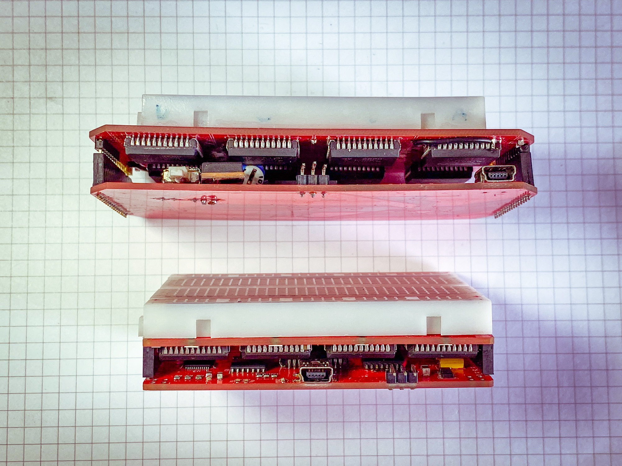
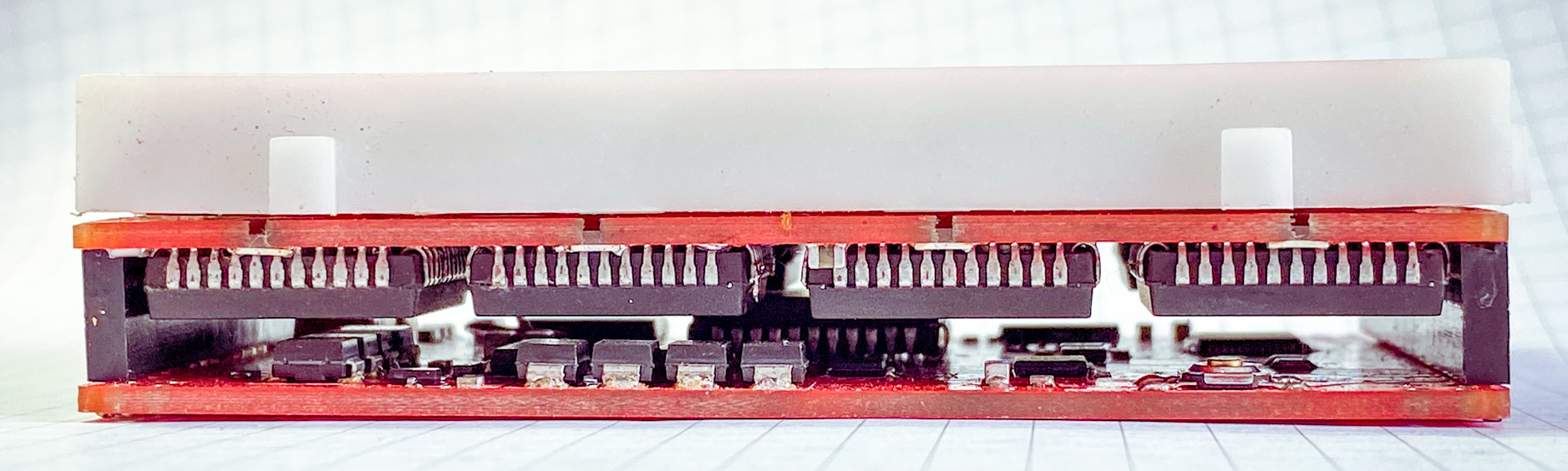
So here's the second board revision. I was showing the last version off to someone and they offhandedly mentioned that it would be cool if the whole thing fit under the breadboard. I knew this was my plan all along, but it forced me to finally design it before the code gets too specific to the original off-the-cuff design and I get stuck with my poor life design choices.
Matrix Board


I found that the most valuable resource when finding paths between rows that aren't directly connected (so they need to make an intermediate hop) are "virtual" breadboard rows that aren't connected to the actual board but connect to the control board below and basically act as the general purpose nodes to do everything else (like reading voltages, connecting to the GPIO on the microcontroller, connecting to a second board, etc.). I put 4 of them in (on chips A, D, E, H), and I don't think that's nearly enough if I want to be able to do a bunch of special function things at once without making the user use some particular set of rows to do certain things. I would really like to make it as simple as "put anything wherever and the board will figure it out."
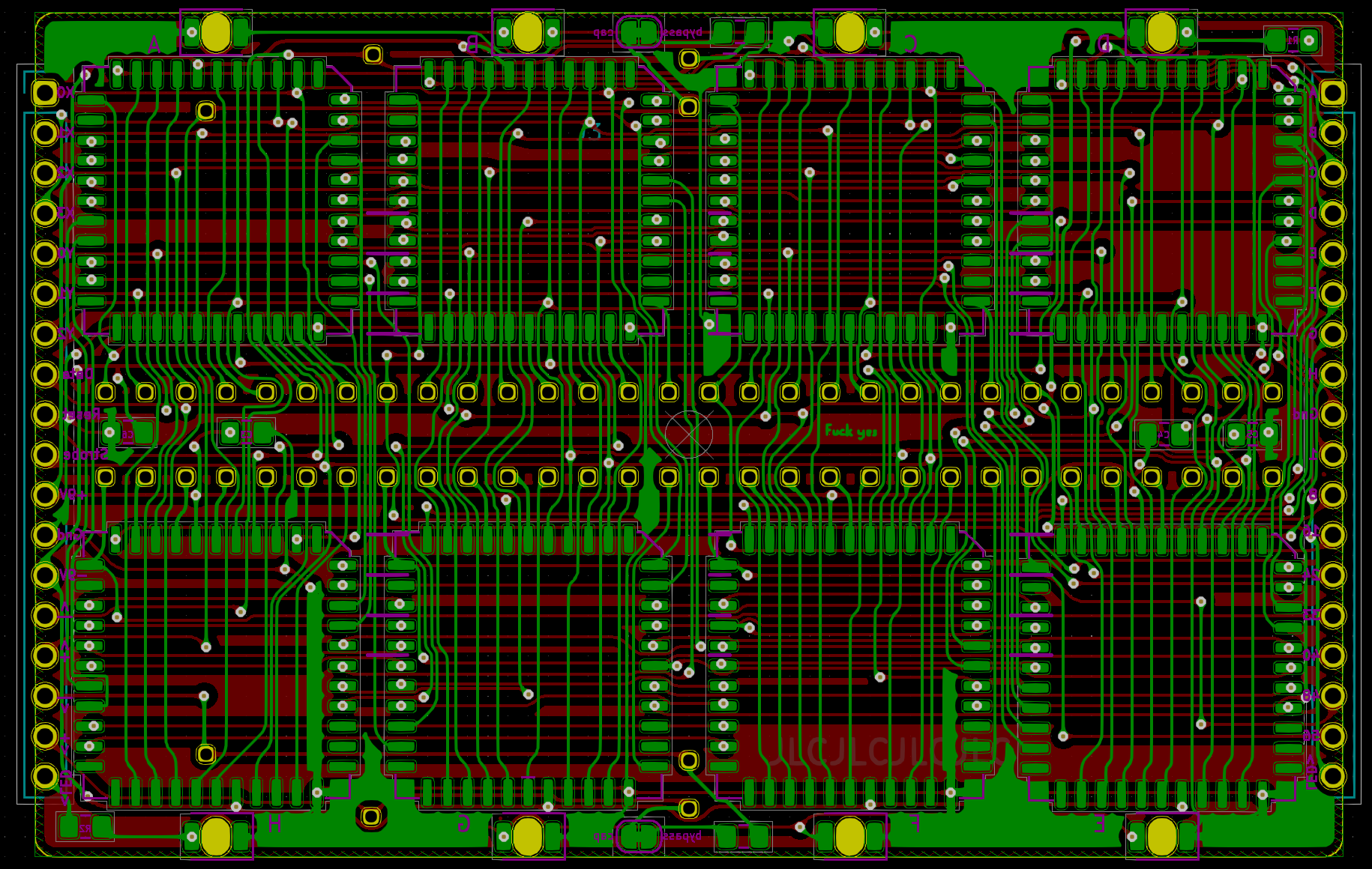
I changed the logical arrangement of the MT8816 crosspoint switches to make the it easier to just hop over the middle space. In the original layout if I wanted to connect top row 5 to bottom row 5, it would always take 2 hops to do that (and these switches each have an on resistance of about 65Ω). Now the bottom rows are flipped so internally the bottom left is 62 and counts down to 33 on the right (note: these are abstracted away to the user by using b1-b30 instead of bigger numbers.)
And just to add some glam I added some reverse mounted LEDs that shine through the top and bottom power rails to show when that rail's power supply is on.
Control Board


I almost entirely redesigned the controller board so it has a ton of whatever the hardware equivalent of syntactic sugar is. The original was kind of thrown together to make sure the concept of using crosspoint switches like that wasn't fundamentally stupid (still not entirely ruling that out, but so far it looks promising.) I also just realized I never did a writeup for the first iteration, and I'm not about to go back and do that just to prove that this board is an improvement.
Power Stuff
Because I'm going to such great lengths to make everything analog, and I already need a negative supply for the crosspoint switches; I decided to make the adjustable power supply for the rails also be able to do negative voltages. The power stuff still needs some work, right now it gets pretty warm when it's running and it really doesn't like it when I remove the matrix board with it on. Presumably because it needs some current draw but I'm not exactly sure why it cares as much as it does (I burned a tantalum cap shaped brand into my finger, you could almost read the markings in it.)
Also, the range of voltages available to each of the 4 rails is fixed. Next revision might include some way to multiplex the power rails (allowing any of them to be negative, right now only the bottom negative rail can do that and it can be changed with a solder jumper) but having looked into it for a while, there doesn't seem to be a way to do it simply enough to outweigh the small utility gained from it. If anyone knows a better way to do this, let me know.
I'm using an LT1054 switched capacitor bipolar voltage converter that takes in +5V and doubles it to +10V and also flips that to -10V. That powers the MT8816s directly and the op amps I'm using for the adjustable voltage supplies. The previous board used inductors for that, and aside from the electrical noise, you could hear them running. I know the frequency they run at is way higher than 20kHz but they must have been resonating with something (or I'm actually part bat) because it was super annoying.
The way I decided to make an adjustable supply that can be controlled by the mcu might be really dumb, but so far it seems to work. I didn't find any well documented examples of people doing it this way, so I'd love to hear from anyone who has or has a good reason why it will cause problems.
I used an MCP4728 DAC that's controlled by I2C and feeds it's 4 outputs into 2 L272D power op amps that can apparently supply 1A each. I used the inverting arrangement with a gain of 1.6 to make the negative supply able to supply 0V - -8V from the 0V - +5V output from the DAC. I put a bunch of low voltage drop schottkys (or is it schottkies? weird) so whatever is happening on the power rails they're supplying shouldn't affect them too much.
What's cool about this setup is that the DAC is fast enough to use this whole circuit as a DDS function generator. That's why I put solder jumpers to disconnect all the bypass caps. I haven't written the code to try this out yet though.

Special Functions
On the control board there's another 8x16 crosspoint switch that I'm using to multiplex the 8 passthrough connections (1 per chip on the top matrix board, but only 4 of them aren't connected to a breadboard pin) to the special functions on the bottom control board.
The special functions are (a checkmark means the firmware is written enough to use it): [ ] 2 ADC channels that can be read by the microcontroller [x] 2 digital potentiometer channels using an MCP4661 [ ] 5 GPIO pins directly connected to the ATmega4809 [x] 2 adjustable power supply channels (0 - 5V, 0 - -8V) [x] 1 ground
The 2 ADC channels go through two 4:1 voltage dividers to bring a possible ±10V input down to ±2.5V and the bottom of those dividers are connected to the V_REF pin on the microcontroller so analog signals can be biased to 0-5V to be read by the 10-bit ADC.
There's an MCP4661 dual 8 bit digital potentiometer that has all 3 pins on 2 independent pots connected to the special function switch. I need to come up with a better interface for setting it in the terminal menu. When I eventually get around to making a GUI for this it will definitely make these more useful. These also come in 4 different ranges (5K, 10K, 50K, 100K) with the same pinout, I currently have the 50K model in there so that means each step is 195 ohms.
The GPIO pins are super interesting, for some reason the ATmega4809 datasheet never mentions the clear superiority of the first 4 pins in port C.
 PC0-3 can do I2C, U(S)ART, 16-bit Timer/Counter, PWM, SPI, and CCL-LUT!
The CCL-LUT means Configurable Custom Logic - LookUp Table, so that means it an simulate an arbitrary logic gate. The analog stuff is covered by pin PE3.
PC0-3 can do I2C, U(S)ART, 16-bit Timer/Counter, PWM, SPI, and CCL-LUT!
The CCL-LUT means Configurable Custom Logic - LookUp Table, so that means it an simulate an arbitrary logic gate. The analog stuff is covered by pin PE3.
Now the tricky part is coming up with a nice way to use those functions through the serial connection. I could probably somehow port the Bus Pirate firmware into some sort of shell, so you could use their awesome Community Firmware (and the red PCB really sells the aesthetic.)
Also, if anyone from Dangerous Prototypes is reading this; I'm dying for updates on (or just an official crushing of my dreams of one day owning) the Bus Pirate Ultra
Communicating With Other Things
On each corner of the board I put a 2x2 header so you can connect these side-by-side and make these into longer board. They communicate via UART with Tx Rx in at the top left and Tx Rx out at the top right. The bottom corners have the 4 unconnected pins from the top matrix on both sides. So you could use these to make connections from one board to the other. As it is currently, having only 4 of these general purpose matrix connections is a huge bottleneck for doing just about anything so I probably need to come up with a way to have more of these free pins in the next revision.
To communicate with the computer, I'm using an MCP2221A to talk to the mcu via a dedicated UART. That chip is also connected to the I2C lines but I'm not sure what I'm going to use that for, maybe I'll have the I2C traffic passed along in some sort of debug mode. It also can send a reset signal from one of it's 4 GPIO lines to the ATmega4809 (with a solder jumper in case that causes problems), which notably is a missing feature of this chip. I could pretend that my choice to to use this was some principled stand against FTDI to cover for the fact that I actually don't remember why I chose this over and FTDI232.

Making It Do Stuff
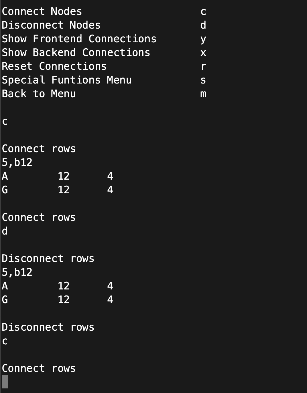
The interface currently sort of follows the general format that a Bus Pirate (and I'm sure a bunch of other things) use; mostly single character commands that present a sub menu. It's amazing how quickly you run out of letters that make sense for a particular command, especially when you have some command you want to be available globally.
Making connections on the board just requires you to type in the two rows you want to connect, separated by a comma. Rows on the bottom are preceded by a 'b' so if you want to connect the 12th row on the top to the 24th row on the bottom you just type
12,b24
In the near future I intend to make a full blown GUI for this, because that's the part that will make this thing actually make your life easier.
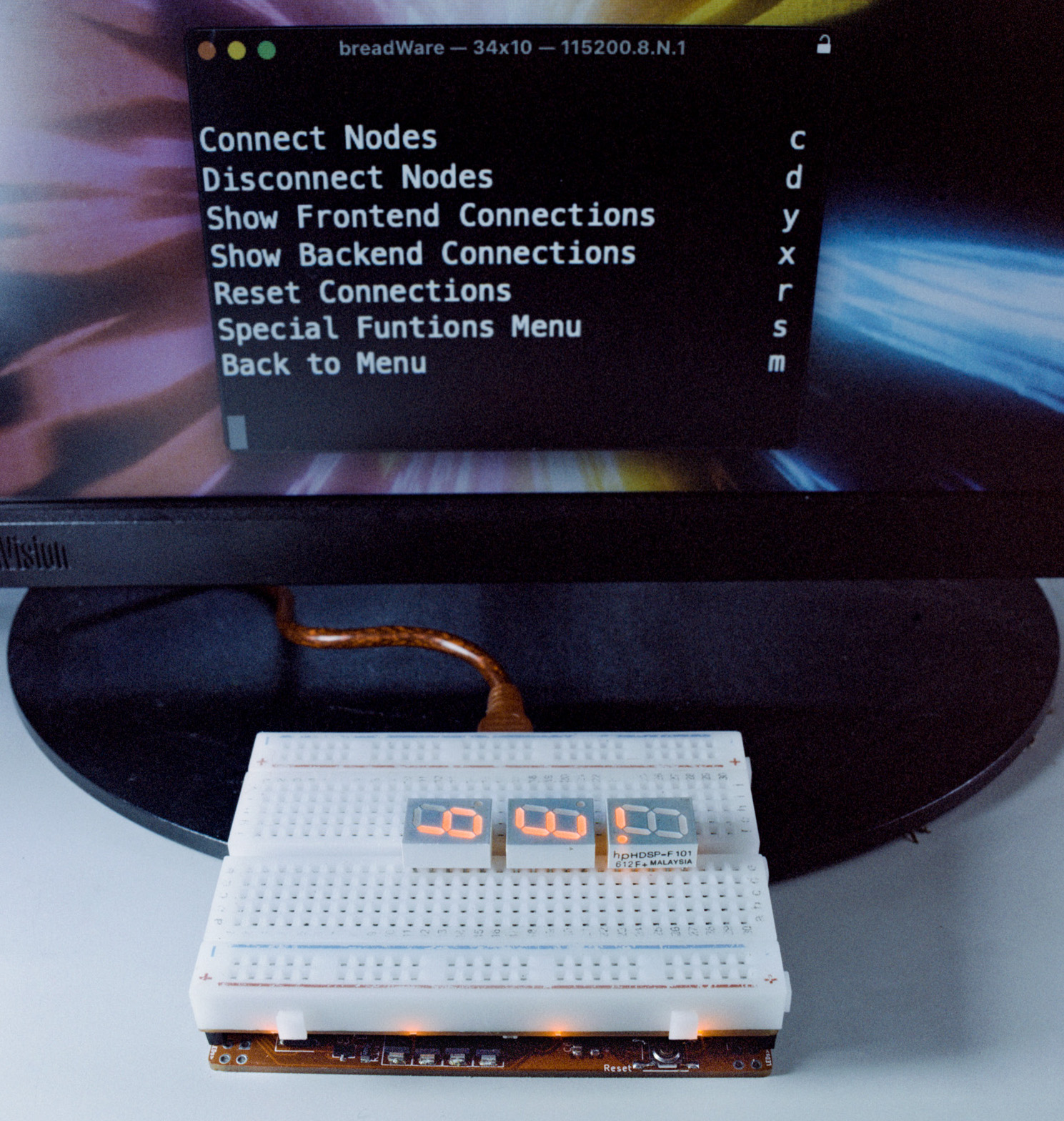
Here are some screenshots the interface:
Connecting Nodes

Disconnecting Nodes
Turning on the power supplies

Using the potentiometer

Showing the frontend connections you've made
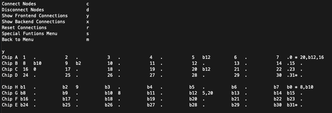
Showing the backend (chip to chip) connections

Here are some extra glamour shots:


mmmmmm melty traces

btw most of these photos were taken on Lomochrome Metropolis with a Mamiya RB67 the two showing the boards separately were taken with an Intrepid 4x5 on cross-processed Provia 100f you can download ridiculously huge scans of these (or my non-documentation related photos) from my Flickr
Here's the documentation for v0.1