RhobanProject / Dynaban
Programming Languages
![]()
This repository contains an open-source alternative firmware for Dynamixel servos.
Note 1: A bad firmware can break your servo, we are not responsible for any damage that could be caused by these manipulations.
Note 2: Using an alternative firmware may void the warranty of your servo.
Robocup 2016 Syposium paper
Supported servos
The currently supported servos are:
-
mx64: MX-64 & MX-64A
Videos
Cursive written "Hello world" with a 6 DoF arm
Building and programming
You'll have to install the arm cross-compilation tools. On debian-like distributions, you can get it with:
    sudo aptitude install build-essential git-core dfu-util openocd python \
        python-serial binutils-arm-none-eabi gcc-arm-none-eabi libstdc++-arm-none-eabi-newlib
If you're running an Ubuntu 14.04 or older, you might need to install the libstdc++-arm-none-eabi-newlib packet by hand. Download link : http://ftp.de.debian.org/debian/pool/main/libs/libstdc++-arm-none-eabi/libstdc++-arm-none-eabi-newlib_4.8.3-9+4_all.deb
Command (if a conflict rises, you can add --force-overwrite to the following line):
sudo dpkg -i libstdc++-arm-none-eabi-newlib_4.8.3-9+4_all.deb
Then, go to the firmware/ directory and edit the Makefile to set the appropriate
BOARD variable, targetting your servo.
You can then run:
make
Use an USB2Dynamixel, a USB2AX or any hardware that allows communication with your servo, and bring an appropriate external power supply. Power it off and type:
make install
This should run the flash script (see scripts/ directory), that will wait for the servo
to boot for flashing it. Then, simply power on your servo.
How to control the servomotor once Dynaban has been flashed?
Anything that works with the default firmware shoud work with Dynaban.
However if you want to use the advanced features we recommend using this modified version of Pypot:
https://bitbucket.org/RemiFabre/pypotdynabanedition/src/master/
The videos above use this code:
https://bitbucket.org/RemiFabre/dear/src/master/
What's new ?
The firmware is on a stable and usable version. The fields that are not mapped below are either considered of little use or considered not doable with the hardware capacities. Nevertheless, these functionalities can be implemented if the need arises. New, powerfull functionalities have been implemented. More on it [below](#Advanced functionnalities)
(Updated 09/09/2015) Putting the CW limit and the CCW limit to the same value already put the servo in wheel mode. Now, putting both limits to 4095 puts the servo in "multi-turn" mode. In that mode, the goal position ranges from -32768 to +32768. Example : if the servo is at position 0° and you ask 720°, the servo will do 2 full rotations before stopping.
Basic functionalities
Here is the list of what is and is not currently implemented when you write into the MX's RAM:
 - LED : mapped.
 - D Gain : mapped.
 - I Gain : mapped.
 - P Gain : mapped.
 - Torque enable : mapped. (default value is 0, you'll need to change the value at start up)
 - Goal Position : mapped.
 - Moving Speed : mapped. Currently, setting a speed will put the motor in wheel mode (if the "mode" value is set to 5, more on the "mode" value below).
 - Torque Limit : not mapped.
 - Present Position : mapped.
 - Present Speed : mapped.
 - Present Load : not mapped.
 - Present Voltage : mapped.
 - Present Temperature : mapped.
 - Registered : not mapped.
 - Moving : mapped.
 - Lock : not mapped.
 - Punch : not mapped.
 - Current : mapped but very hard to exploit because it is very noisy and the noise
   is not the same if the motor is going CW or CCW.This is the biggest issue we
   encountered, more on that problem in the notes.
 - Torque Control Mode Enable : mapped.
 - Goal Torque : mapped but does not work that well due to the bad current measurement.
 - Goal Acceleration : NOT mapped.
Here is the list of what is and is not currently implemented when you write into the MX's EEPROM (flash):
- Model Number : mapped.
- Version Of Firmware : mapped.
- ID : mapped.
- Baud Rate : mapped.
- Return Delay Time : not mapped.
- CW and CCW angle limits : mapped. Both at 0 means no limits.
- Highest Limit Temperature : not mapped Currently hard set to 70 degrees.
- Lowest and highest Limit Voltage : not mapped.
- Max Torque : not mapped.
- Status Return level : not mapped.
- Alarm led : not mapped.
- Multi turn offset : not mapped.
- Resolution Divider : not mapped.
Advanced functionalities
One of the motivations behind this project was to have full control over our hardware. Once the basic stuff was working, we started playing with more advanced funtionalities.
RAM mapping extention
The RAM chart of the MX-64 ends with the field "goalAcceleration" on the adress 0x49. On the Dynaban firmware, the chart is increased with the following fields :
unsigned char trajPoly1Size;            // 0x4A
float         trajPoly1[DXL_POLY_SIZE]; //[0x4B
                                        //[0x4F
                                        //[0x53
                                        //[0x57
                                        //[0x5B
unsigned char torquePoly1Size;          // 0x5F
float         torquePoly1[DXL_POLY_SIZE];//[0x60
                                        //[0x64
                                        //[0x68
                                        //[0x6C
                                        //[0x70
uint16        duration1;                // 0x75

unsigned char trajPoly2Size;            // 0x76
float         trajPoly2[DXL_POLY_SIZE]; //[0x77
                                        //[0x7B
                                        //[0x7F
                                        //[0x83
                                        //[0x87
unsigned char torquePoly2Size;          // 0x8B
float         torquePoly2[DXL_POLY_SIZE];//[0x8C
                                        //[0x90
                                        //[0x94
                                        //[0x98
                                        //[0x9C
uint16        duration2;                // 0xA0
unsigned char mode;                     // 0xA2
unsigned char copyNextBuffer;           // 0xA3
bool          positionTrackerOn;        // 0xA4
bool          debugOn;                  // 0xA5
uint16 staticFriction;                  // 0xA6
float i0;				    // 0xA8
float r;				    // 0xAC
float ke;                               // 0xB0
float kvis;                             // 0xB4
uint16 statToCoulTrans;                 // 0xB8
float coulombCommandDivider;            // 0xBA
int16 speedCalculationDelay;	    // 0xBE
float ouputTorque;                      // 0xC0
float outputTorqueWithoutFriction;      // 0xC4
unsigned char frozenRamOn;              // 0xC8
unsigned char useValuesNow;             // 0xC9
uint16 torqueKp;                        // 0xCA
float goalTorque;			    // 0xCC
Using the field 'mode' :
A servo using the Dynaban has diferent mode it can be in. You can set the desired mode by writing a number in the "mode" field (adress 0xA2 in the RAM).
- 0 : Default mode. Uses the PID to follow the goal position. The behaviour should be almost identical to the default firmware
- 1 : Predictive command only. Follows the trajectory set in the traj1 fields but only relying on the model of the motor. This mode can be useful when calibrating the model
- 2 : PID only. Follows the trajectory set in the traj1 fields but only relying on the PID.
- 3 : PID and predictive command. Follows the trajectory set in the traj1 fields using both the PID and the predictive command. This should be the default mode when following a trajectory
- 4 : Compliant-kind-of mode. In this mode, the servo will try to act compliant
Predictive control background :
One very big limitation of the default firmware is that the only control loop that is available is a PID (which is already an enhancement compared to the RX family that has only a P). A PID is meant to compensate the differences between what is predicted by the model of our system and what actually happens. Those differences come from :
- The model limitations (how is the friction modelized? Is the inertia taken in concideration? Etc.)
- The loopback imprecisions (accuracy and delay)
- The external pertubations.
The default firmware has no model, so the PID has a lot of work to do !
Let's say that we want to follow a predefined trajectory, like a min-jerk trajectory. The servo is attached to a weight of 270g at a distance of 12cm. With a PID-only approach, we compare the ideal trajectory with 3 actual trajectories the motor did with orders sent at 25Hz, 50Hz and 1000Hz :
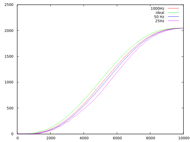

Even though the static precision is perfect (the I part of the PID ensures a null static error), the dynamic precision is not and even reaches ~8° when the speed is maximum. In a 6 DOF robotic linear arm, where the errors stack up, the lack of dynamic precision is prohibitive. Increasing the frequency of the orders improves the quality of the result but the enhancement is capped, there would be almost no diference in quality between the 1000Hz curve and a 2000Hz curve. By construction, a PID-only approach will always lag behind a moving command.
In order to overcome this problem, the Dynaban firmware implements a model of the motor. More precisely :
- A model of the electric motor (essentialy the relationship between input voltage, rotation speed and output torque)
- A model of the frictions (with an estimation of the static friction and the coulomb friction)
- An inertial model
After tuning the model, we managed to get decent results with a full open loop approach :

And almost perfect results (< 0.4°) when we combine the model and the PID :

How to use the predictive control? :
The idea here is to tell the servo what it will have to do in the near future and let it try to match it. More precisely :
- The servo needs to know the positions it should be at in the near future
- The servo needs to know the torques it should output in the near future
In order to achieve that, you'll have to :
- Choose the duration of the spline (i.e. what we called "near future"). Beware though, the duration is an integer in tenth of milliseconds (10000 is 1 s)
- Send a polynome describing the expected positions for the duration. You can choose the degree of the polynome between 0 and 4. If the polynome looks like a0 + a1t + a2t², then you'll have to send the 3 floats a0, a1 and a2 to the servo and set trajPoly1Size to 3.
- Send a polynome describing the expected torque for the duration. The 2 polynomes don't need to be of equal degrees.
Once these informations have been set, the servo will try to follow the trajectory as soon as the field "mode" is set to 1, 2 or 3 (cf [Using the field mode](#Using the field mode)).
When the trajectory ends, the field "mode" will automatically be set to 0 (default, position control mode). Basically, the servo will try to stay where it landed at the end of the trajectory. [Unless you want to continue your trajectory with an other one.](#How do I smoothly continue a trajectory after the first one ended ?)
How do I smoothly continue a trajectory after the first one ended ?
As you can notice in the [RAM mapping extention](#RAM mapping extention), the fields needed to use the predictive control are present twice. Once under the name of traj1 and once under the name of traj2 (trajPoly2Size, trajPoly2, torquePoly2, etc). The fields traj2 are a buffer that will be copied into the traj1 fields once the traj1 finishes.
For this behaviour to happen, you'll have to set copyNextBuffer to 1. copyNextBuffer is automatically set to 0 when the buffer is copied. So, in order to continue a trajectory several times, the procedure would be :
- Update traj2 and set copyNextBuffer to 1
- Once traj1 is finished, update traj2 and set copyNextBuffer to 1
- Once traj1 is finished, update traj2 and set copyNextBuffer to 1 etc.
The transitions between the trajectories should be made in a way that ensures the continuity of both torque and position trajectories and their derivates. Don't do this :>)

Model parameters :
Dynaban uses a model of the electrical motor and a model of friction. These models have parameters that can be adjusted by the user with the following fields : (TO DO : explain a bit the model)
- staticFriction
- i0
- r
- ke
- kvis
- statToCoulTrans
- coulombCommandDivider
Speed calculation :
The speedCalculationDelay field is expressed in ms and affects how the speed is calculated. The greater speedCalculationDelay is, the greater the granularity on the speed calculation and vice-versa. The current speed calculation implementation is approximately equivalent to : speed(t) = position (t) - position (t - speedCalculationDelay)
The granularity (or LSB) of the speed is as follows :
LSB = 1000/speedCalculationDelay
Where LSB is in steps/s and speedCalcultaionDelay is in ms.
=> With a speedCalculationDelay of 50 ms, the speed value will be a multiple of 20 steps/s (1.76 deg/s).
There is a pitfall though, if you set the speedCalculationDelay so high that the servo is fast enough to do more than half a rotation during speedCalculationDelay, then bad things will happen. This could be solved by the firmware but the cons seem to outweight the pros since this only happens with extreme values.
Respect the following formula and it will be fine:
speedCalculationDelay < 2048 * 1000 / maxServoSpeed
Where speedCalculationDelay is in ms and maxServoSpeed is in steps/s.
8096 steps/s (2 rotations/s) is a comfortable max speed for a MX64 => maximum value of speedCalculationDelay = 252 ms
Miscellaneous :
When the debugOn field is set to 1, debug information will be printed through the serial interface every time something is written by the user on the serial interface.
Don't mind the positionTrackerOn field, it's used by us when testing and benchmarking but it's not meant to be user-friendly. The idea here is to store information (typically the present position) on the RAM as fast as possible and, only when the experience is over, send the data through the serial port. The position sensor is currently read at 1KHz (could be read up to 10KHz) which is way more than what's achievable through the dxl protocol.
Is using floating point values a good idea ?
Dynaban started on a MX-64 which is powered by a Cortex M3 with a 72MHz clock. The embedded micro controller doesn't have a FPU, which means that both floating point multiplications and floating point divisions take a lot of time to process. We did some benchmarks. Measures were done with a hardware timer with a precision of 0.1 ms : 1 000 000 floating point multiplications done in 1.1431 seconds, which implies ~82 clock cycles per multiplication. 1 000 000 floating point divisions done in 1.0995 seconds, which implies ~79 clock cycles per division.
~80 cycles for an operation is a lot, but Dynaban works well even though the hardware is ticked at 1 kHz. Using floats when talking torques and following timed trajectories is handy but when Dynaban will be implemented on devices with lesser uC performances, we'll use fixed point arithmetics instead.
To do :
 - Modify how the speed is calculated. The speed ranges from 0 to 1023 (and 1024 to 2047
 for the other direction). 1023 is 117.07rpm, 1 is 0.114rpm which is about 8 steps/s
 (the magnetic encoder has 4096 steps). Therefore, to be able to measure a speed of
 0.114rpm, we need to wait 128ms. This is very bad when you think "control loop", since delays
 create instability. The easy solution is to reduce precision (unless you're using your
 MX to build a clock, not sure it's useful to get a precision of  0.114rpm). A better
 solution is to reduce precision (ie reduce delay) as speed goes up.
 - Make it possible to set a speed in joint mode (connect control
 loops to each other)
 - Write documentation for this new portion of RAM :


bool          positionTrackerOn;        // 0xA4
	bool          debugOn;                  // 0xA5
	uint16 staticFriction;                  // 0xA6
float i0;								// 0xA8
float r;								// 0xAC
float ke;                               // 0xB0
float kvis;                             // 0xB4
uint16 statToCoulTrans;                 // 0xB8
float coulombCommandDivider;            // 0xBA
int16 speedCalculationDelay;			// 0xBE
float ouputTorque;                      // 0xC0
float outputTorqueWithoutFriction;      // 0xC4
unsigned char frozenRamOn;              // 0xC8
unsigned char useValuesNow;             // 0xC9
uint16 torqueKp;                        // 0xCA
float goalTorque;						// 0xCC
License
This is under CC by-nc-sa license