atomic14 / Esp32_audio

ESP32 I2S ADC Sampling
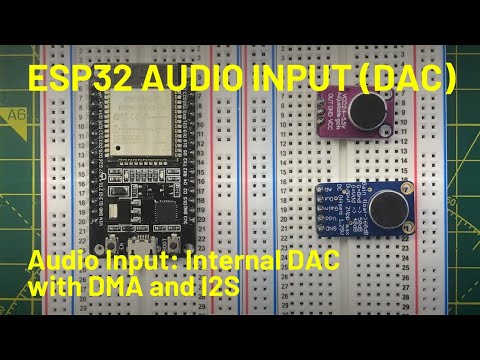
Explanatory video of the analog boards here (MAX9814 and MAX4466) here
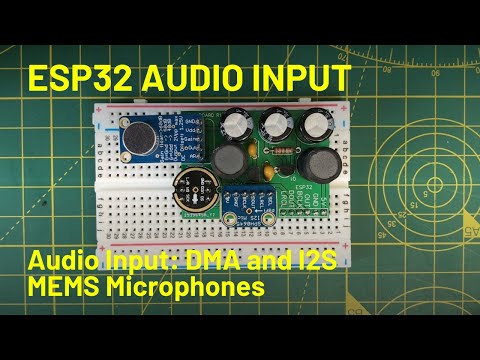
And for the two I2S boards (SPH0645 and INMP441) here
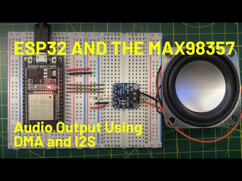
For audio output we can use the MAX98357A boards - there's a explanatory video here
This project demonstrates how to use the ESP32 built-in Analog to Digital Converters and I2S for capturing audio data and for audio output..
There are four projects in this repository: loop_sampling, i2s_sampling, i2s_output and server.
server
This is a simple node server that writes the samples received from the ESP32 to a file.
Check the README.md file in the server folder for detailed instructsions.
You will need to have node and yarn. You may already have these on your system.
Check with:
node --version
yarn --version
Then just run:
cd server
yarn
To install the dependencies. And
cd server
yarn start
When you want to run the server.
loop_sampling
This project shows how to use the Arduino analogRead function and the Espressif adc1_get_raw function.
It also demonstrates how to get a calibrated value back from the ADC to give you the actual voltage at the input.
i2s_sampling
This project handles both analogue devices (such as the MAX4466 and the MAX9814) and I2S devices (such as the SPH0645 and INMP441).
This project demonstrates how to use the I2S peripheral for high-speed sampling using DMA to transfer samples directly to RAM.
We can read these samples from the internal ADC or from the I2S peripheral directly.
Samples are read from the DMA buffers and sent to a server running on your laptop/desktop machine.
The current set of pin assignment in the code are:
ADC
| Function | GPIO Pin | Notes |
|---|---|---|
| Analogue input | GPIO35 | ADC_UNIT_1, ADC1_CHANNEL_7 |
I2S
| Function | GPIO Pin | Notes |
|---|---|---|
| bck_io_num | GPIO_NUM_32 | I2S - Serial clock |
| ws_io_num | GPIO_NUM_25 | I2S - LRCLK - left right clock |
| data_in_num | GPIO_NUM_33 | I2S - Serial data |
i2s_output
This example shows how to drive an I2S output device - I've tested this against the MAX98357 breakout board from Adafruit - https://learn.adafruit.com/adafruit-max98357-i2s-class-d-mono-amp
There is an example WAV file that can be played or you can play a simple sin wave through the output.
To play the WAV file you will need to download the file to the SPIFFS file system.
This is now annoyingly hard to find on platform.io - watch this video to see how to find it.
The pins currently configured are:
| Function | GPIO Pin | Notes |
|---|---|---|
| bck_io_num | GPIO_NUM_27 | I2S - Serial clock |
| ws_io_num | GPIO_NUM_14 | I2S - LRCLK - left right clock |
| data_out_num | GPIO_NUM_26 | I2S - Serial data |