Esp8266 1-Channel Relay Board with MQTT
Sketches for an Esp8266-01 STC 15f104W powered 1-channel relay board to be controlled remotely using an MQTT broker as communication bus without modifying physically the device nor using any third part android app.
TL;DR
basic/basic.ino - simple file to make the board switch ON or OFF every ~2 seconds
simple_mqtt/stc_15f104W.ino - example to use single relay board and an MQTT broker
multi_relay/stc_15f104W.ino - code by @sehraf to allow using boards with 4 relays
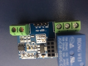
The board
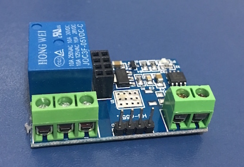
I bought this chinese board from a local retailer. Surprisingly or not the device was delivered to me whitout any sort of technical instructions. Following the description in the retail's online store, I realized that the board has a single channel relay and an 8-pin slot to plug an esp8266-01 into. In addition to voltage regulators and other passive components, the board is equipped with one STC 15f104W chip. STC 15f104W is a microcontroller and, in this board, this microcontroller is responsible for receive commands from the ESP and forward them to the relay.
Manufactor page is here
Esp8266-01
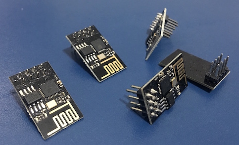
Espressif Esp8266 model 01 is a revolutionary device that allows everyone to build real IoT solutions at low cost. The one I have used in this example is the second generation of model 01. It is compatible with board slot layout but it has 1 Mb of flash memory, a valuable resource to build customizable solutions and to store persistent tracking records.
Trying to use the board
My first thought when I buyed this device was: "It should be easy to set up". Sadly, I was completely wrong. The absense of official documentation put me alone in an obscure journey of emptiness and doubt. After my searches, I ended up with two concrete (but terribly ugly) alternatives: 1) using an crap Android App to control the board or 2) changing the board circuit to make it more friendly to use. Hopefuly, I found a way to get the device running without any Android App or physical violation such as soldering or desoldering. The three alternatives area explained below.
Option 1 - Android App
In the manufactor page I actually found a link for a manual/instructions. But I couldn't find documents in the Baidu website where the link redirected me out:
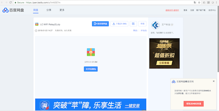
Without even a device identification, I digged around the internet finally finding a bizarre MS Word document with few and messy instructions about how to control the board. According to this document, it is required to use a crapy android app to send AT commands to the ESP in order to make the relay to switch. This way wasn't an option for me since I have planned to use the board into a home automatation MQTT environment. Thus, I have discarded the word doc. But if you are interested I found a tutorial which seems to be just a copy of it: https://www.hackster.io/makerrelay/esp8266-wifi-5v-1-channel-relay-delay-module-iot-smart-home-e8a437
Option 2 - Physically change the board
Searching a bit more, I found another post instructions explaining how to remove resistors and soudering jumps in order to control the relay "in regular fashion" by PIN 2 bypassing STC 15f104W. Again this wasn't an option for me since I don't like to change constructive devices features in so intrusive way, at least for real applications.
Option 3 - The solution
Reading the MS word document again I realized that the strings sent by Android Application to the ESP (into AT commands) were basically forwarded throughout RXTX interface to the board. To check my assumptions I wrote a pretty straightforward application just to ESP send these strings to the board:
void setup() {
  Serial.begin(9600);
}

void loop() {
  byte close[] = {0xA0, 0x01, 0x01, 0xA2};
  Serial.write(close, sizeof(close));
  delay(2000);

  byte open[] = {0xA0, 0x01, 0x00, 0xA1};
  Serial.write(open, sizeof(open));
  delay(2000);
}
After uploaded the code to ESP and plug it in the board the relay began to switch into two states every 2 seconds. Gotcha!
Almost done, now we know how to control the relay so let's plug it in the MQTT bus.
Making the board a MQTT subscriber
If you are familiar with MQTT platform, you know that each device can act as a publisher or a subscriber (or both). A publisher is something that inserts (or publishes) new messages into the bus (the MQTT broker). The message is labeled with a exclusive identifier called TOPIC. A subscriber client consome the messages but just the only ones sent for the TOPIC which it has been subscribe. Thus, the topic is like an address that the MQTT broker uses to deliver the right messages from the publishers to the subscribers.
So, in this architecture, the board can act as a subscriber receiving messages from the MQTT Broker. Thus, all messages sent for a specific 'topic' will be delivered to the board. For example, if the board subscribe to the topic "/myRelay-001/command", a message published by another MQTT client like:
$ mosquitto_pub -t "/myRelay-001/command" -u "myuser" -P "mypassword" -m "CLOSE"
will be delivered to the board. So, the remain task is to write a subscriber MQTT client to receive that kind of message and responding in according (opening/closing).
If you are new on MQTT a good point to start is to install mosquitto on ubuntu 16.04 and play with the embedded publish and subscriber clients.
Coding the MQTT subscriber
Complete code can be found here in this repository. Anyway, the main points are explained for your convenience:
Use the right headers
Here you will need the both PubSubClient and the Esp8266 Wifi API. The PubSubClient library can be found here. If you are starting with Esp8266 programming you can look for tutorials like this one to setup the Arduino IDE with ESP libraries.
#include <PubSubClient.h>
#include <ESP8266WiFi.h>
Create the client
MQTT protocol runs in top of the application layer of TCP/IP network and of course you need a working Wifi network and credentials in order ESP can connect in.
WiFiClient wifiClient;
PubSubClient client(wifiClient);
Write the setup and loop
The setup is pretty simple. Take attention to the Serial baudrate. It must be 9600 to the board understand what the ESP is sending.
  Serial.begin(9600);
  delay(10);
  Serial.println("Let' start now");
The loop just verify the connection status and reconnects whenever necessary. Do not forget the client.loop() line otherwise your MQTT subscriber client will not be notified!
  if ( !client.connected() ) {
    connect();
  }
  client.loop();
Connect as subscriber
Here one of most important aspect is the line client.subscribe(topic); which define the role of the client in the MQTT protocol as a subscribe; Also line client.setCallback(callback); that defines which function will be called out when a message arrives.
void connect() {
  while (!client.connected()) {
    status = WiFi.status();
    if ( status != WL_CONNECTED) {
      WiFi.begin(WIFI_SSID, WIFI_PASSWORD);
      while (WiFi.status() != WL_CONNECTED) {
        delay(500);
        Serial.print(".");
      }
      Serial.print("Connected to ");
      Serial.println(WIFI_SSID);
    }
    client.setServer(mqttServer, mqttPort);
    client.setCallback(callback);
    if (client.connect(deviceId, mqttUser, mqttPassword)) {
      client.subscribe(topic);
      Serial.println("Connected to MQTT Server");
    } else {
      Serial.print("[FAILED] [ rc = ");
      Serial.print(client.state() );
      Serial.println(" : retrying in 5 seconds]");
      delay(5000);
    }
  }
}
Write the callback function
This is the callback function. The main task is unwrap the payload and check if it is a OPEN or CLOSE operation. The code is pretty straighforward but one relevant point is: you should to avoid consecutives OPEN-CLOSE operation in short time. Let's imagine that hundred of published messages arrives in the device every second. In this scenario the relay will make hundred of Open-Close operations in a short time. This scenario is harmful. Consecutives open-close cycles will generate heat and maybe start fire. So, to avoi it, after each operation is stored the timestamp. Another operation is performed just in case the delta time is acceptable ( MIN_OPERATION_INTERVAL constant).
unsigned long lastOperation;
const long MIN_OPERATION_INTERVAL = 2000L;

const String openString = "OPEN";
const String closeString = "CLOSE";
byte close[] = {0xA0, 0x01, 0x01, 0xA2};
byte open[] = {0xA0, 0x01, 0x00, 0xA1};

void callback(char* topic, byte* payload, unsigned int length) {
    signed long now = millis();
    long deltaTime = now - lastOperation;
    if (deltaTime > MIN_OPERATION_INTERVAL) {
      String message = "";
      for (int i = 0; i < length; i++) {
        message = message + (char)payload[i];
      }
      if(message == openString) {
        Serial.println("Performing open command");
        Serial.write(open, sizeof(open));
        lastOperation = now;
      } else if(message == closeString) {
         Serial.println("Performing close command");
        Serial.write(close, sizeof(close));
        lastOperation = now;
      }
  } else {
    Serial.println("Operation denied right now. Try again later.");
  }
}
Troubleshooting
Something in my head says that this troubleshooting section should be long. But I'll try to be short.
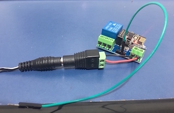
Power Supply
After programming ESP you should to connect it into the board and power up the board by a 5V reliable power source unit. In my tests I've used a 2 Amp PSU. Esp itself drain energy and the relay needs enery as well to perform its mechanical operation. I don't tried to power the board only using with the energy from USB port and I guess it is a bad idea even for test purposes. So, if relay do not open/close one good shoot could be to check the power source.
Cables
Every connection must be revised BEFORE you turn on your Power Supply. In some cases, like the TX-RX connection, inverted cables are just a temporary inconvenient: after you realized that the cables are switched just fix the connection and go on. But if you do a mistake with VCC and ground cables you will damage your device seriously. So, take a breath and review your connection.
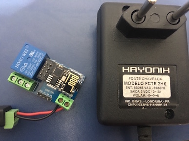
The power supply I have used.
DISCLAIMER: Remember to review your connections BEFORE turn up power.
The right serial baudrate
Is 9600. If you don't meet it the board will not work. And there no way to change this setting.
in If everything is right (WIFI and MQTT credentials for example) than the way to go is to check ESP in operation inside the board. A nice thing in this board is 4 pins for VCC, GND, RX and TX. If you want see serial output from ESP (and maybe error messages) you can connect your FTDI there: GND-GND, TX-RX, RX-TX. DISCLAIMER: DO NOT CONNECT VCC-VCC or your USB port can be damaged.
My code doesn't work when I plug Esp in the board - part 2
Yes it is crazy but this board has a severe design issue: the ESP Antenna is strongly atennuated by the board making it unsable. Yes, when you plug the ESP in the board the ESP antenna doesn't work and ESP cannot connect to WIFI. It is crazy I know but I just bought the board, I didn't designed it. My workaround was to improvise a secondary antenna. Just connect a free jump in RX connector and ESP will be able to connect to your WIFI again.
An improvised antenna just in case if you have a hard day like my one today
Acknowledgment
I like to say THANK YOU to people from China who have design and build so lovely device and make my day full of fun =D