This repo is deprecated. This project now lives here (as of March 2022): https://github.com/CharlestonRobotics/ChIMP
HoverBot
Rugged radio-controlled self-balancing robot using hoverboard hub motors.
Table of contents
- Key Components
- External Dependencies
- Videos
- Control Scheme
- Schematic
- Wiring
- Press
- Additional Documentation
Key Components
- An Arduino Mega https://store.arduino.cc/mega-2560-r3. Using the Mega because the project needs three hardware interrupt pins to decode the RC receiver's PWM signals.
- A Bosch BNO055 IMU https://www.adafruit.com/product/2472. Gives ready-to-use tilt angle estimation as well as gyro and accelerometer raw readings.
- An ODrive motor controller (48V) https://odriverobotics.com/shop/odrive-v35. Enables very smooth current control for the two motors.
- Two hoverboard hub motors (easy to source from ebay). Very affordable, powerful and easy-to-use motors.
External Dependencies
Arduino
- Metro https://github.com/LuSeKa/Metro
- ODriveArduino https://github.com/madcowswe/ODrive
- Adafruit_Sensor https://github.com/adafruit/Adafruit_Sensor
- Adafruit_BNO055 https://github.com/adafruit/Adafruit_BNO055
Python
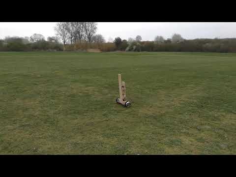
Videos
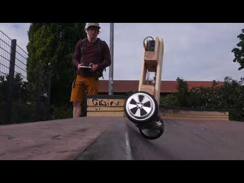
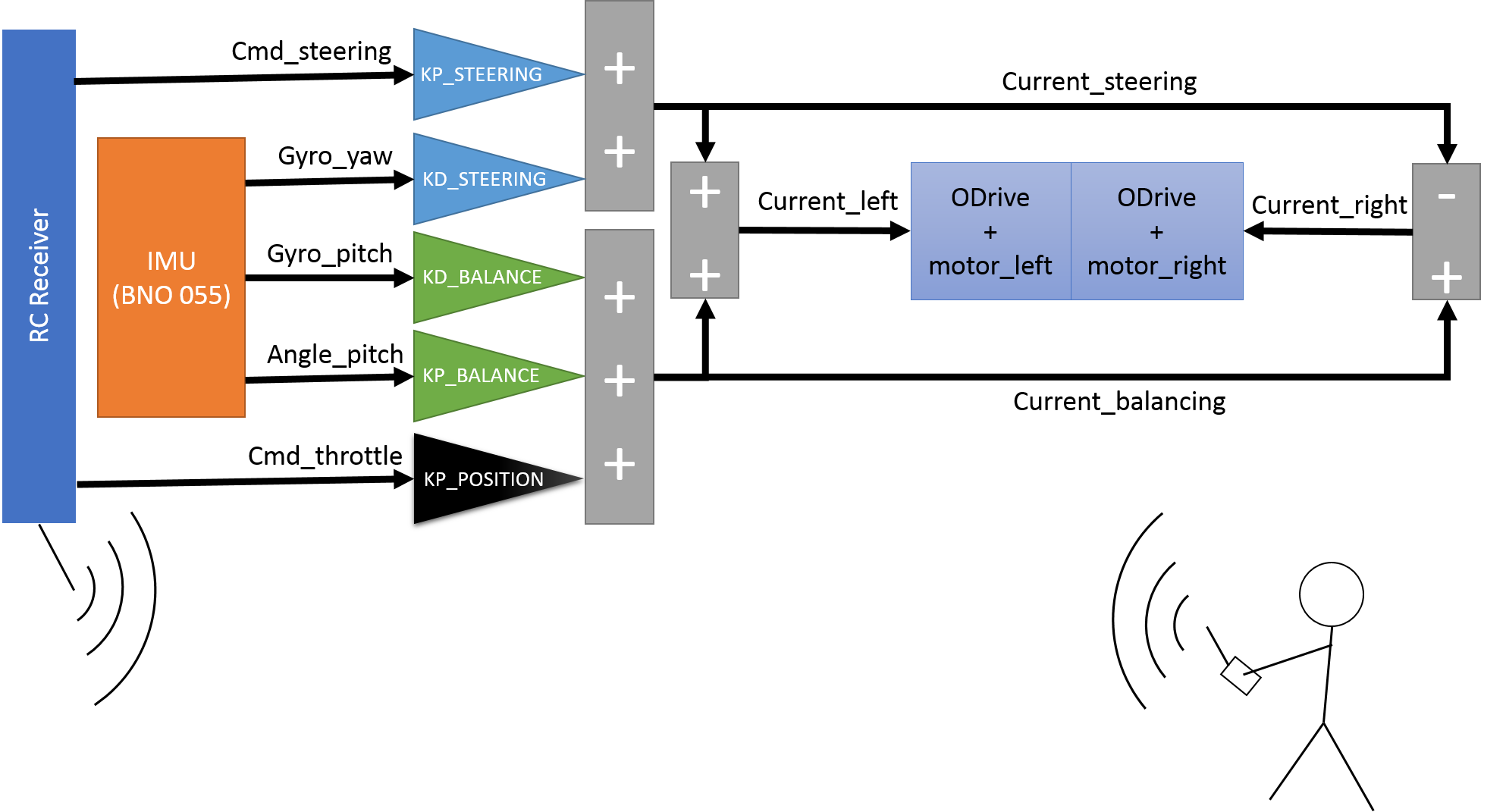
Control Scheme
The ODrive is operated in current control mode. The current is computed by the Arduino from the pitch and pitching velocity to control balancing, from the throttle command to control the forward and backward velocity, and from the steering command and the yaw velocity to control the steering. The controller is tuned with five parameters listed in the config.h file.
A problem of this control scheme is that the onboard controller does not get velocity feedback. If the vehicle goes too fast, the balance controller cannot compensate a forward fall anymore, and it will fall over eventually. The human at the sticks therefore needs to make sure that the velocity is kept sufficiently slow.
Schematic
The following diagram roughly explains the data flow and types of electrical connections.

Wiring
Note that the wiring is Highly Experimental and just a Proof-of-Concept.


The wiring connects the wheel motors and their hall sensors with the ODrive, the ODrive to the Arduino and the Arduino to the IMU (sitting on a breadboard) and to the RC receiver.
ODrive

The wiring of the ODrive is explained on the ODrive website (that has very nice docs overall!): https://docs.odriverobotics.com/#wiring-up-the-odrive
Power and motors
The ODrive is powered from the battery via its DC clamps (thick black and red cables on the left), and each motor's three phases (A, B, C, blue, yellow and green) are connected to one of its motor output clamps (M0 and M1). The order in which the motor wires are connected does not matter, the ODrive figures this out by itself during calibration.
Auxiliary resistor
If HoverBot is powered from batteries without built-in battery management system (PMS), no auxiliary breaking resistor is required (the ODrive dumps recuperated energy into the battery). If the batteries have a PMS (such as the ones usually found in a hoverboard), using the auxiliary resistor might prevent overvoltage errors.
Hall sensors
Each hoverboard motor comes with hall sensors that tell the ODrive when to power which of the three phases. Each hall sensor has five wires: Two for power (5V, usually red and GND, usually black) and three for signal (often blue, yellow and green). A motor's hall sensors are connected using extension cables to the corresponding sensor inputs (M0 and M1) on the ODrive's J4 connector. The three signal lines are connected to inputs A, B and Z where the order again does not matter. Note that it might be necessary (depending on the version of the ODrive) to add some a 22nF capacitor between each of the three signals and ground for signal integrity (insulated with hot glue), as is mentioned here: https://discourse.odriverobotics.com/t/encoder-error-error-illegal-hall-state/1047/6
5V power
The ODrive powers the 5V power supply of all other components, so its GND (black cable on the J3 connector) and 5V (red cable on the J2 connector) are connected to a breadboard that acts as power distribution.
UART
The ODrive communicates with the Arduino via the serial port, or UART. The UART pins are GPIO 1 (yellow) and GPIO 2 (white), as explained here (GPIO 1 connects to the Arduino's RX, GPIO 2 to the Arduino's TX): https://docs.odriverobotics.com/interfaces#ports
IMU
 The IMU only requires two wires for 5V power (red) and GND (black) from the breadboard and two wires for the I2C connection to the Arduino, connecting the IMU's and the Arduino's SDA (white) and SCL (left green). https://learn.adafruit.com/adafruit-bno055-absolute-orientation-sensor/pinouts
RC Receiver

The receiver is powered by 5V (red) and GND (blue) from the breadboard and each of the PWM signal outputs (three for the HoverBot) are connected to one of the Arduino's inputs that are capable of hardware interrupts. The fact that three hardware interrupt pins are needed is the reason why HoverBot uses an Arduino Mega rather than a smaller and cheaper Uno or Nano (see https://www.arduino.cc/reference/en/language/functions/external-interrupts/attachinterrupt/). The pins used are 2 (orange), 3 (yellow) and 18 (green), and their channel assignment is set in the first lines of the config.h file: https://github.com/LuSeKa/HoverBot/blob/master/config.h
Arduino
The Arduino is powered from 5V (red) and GND (black) from the breadbaord. Apart from the connections already mentioned, the Arduino's USB port should be accessible for programming.
Press
- IEEE Spectrum Video Friday (07 June 2019)
- Arduino Blog (10 June 2019)
- Weekly Robotics #45 (30 June 2019)