Matsemann / Impossible Objects
Programming Languages
Impossible Objects
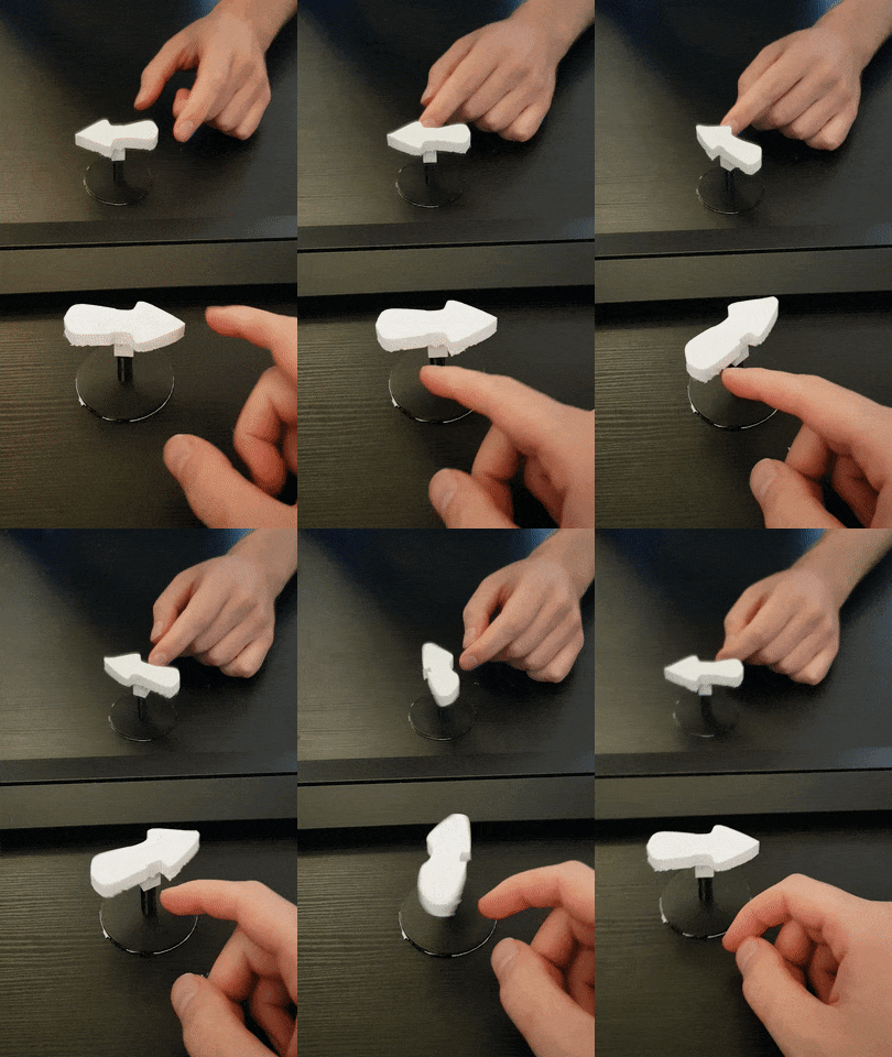
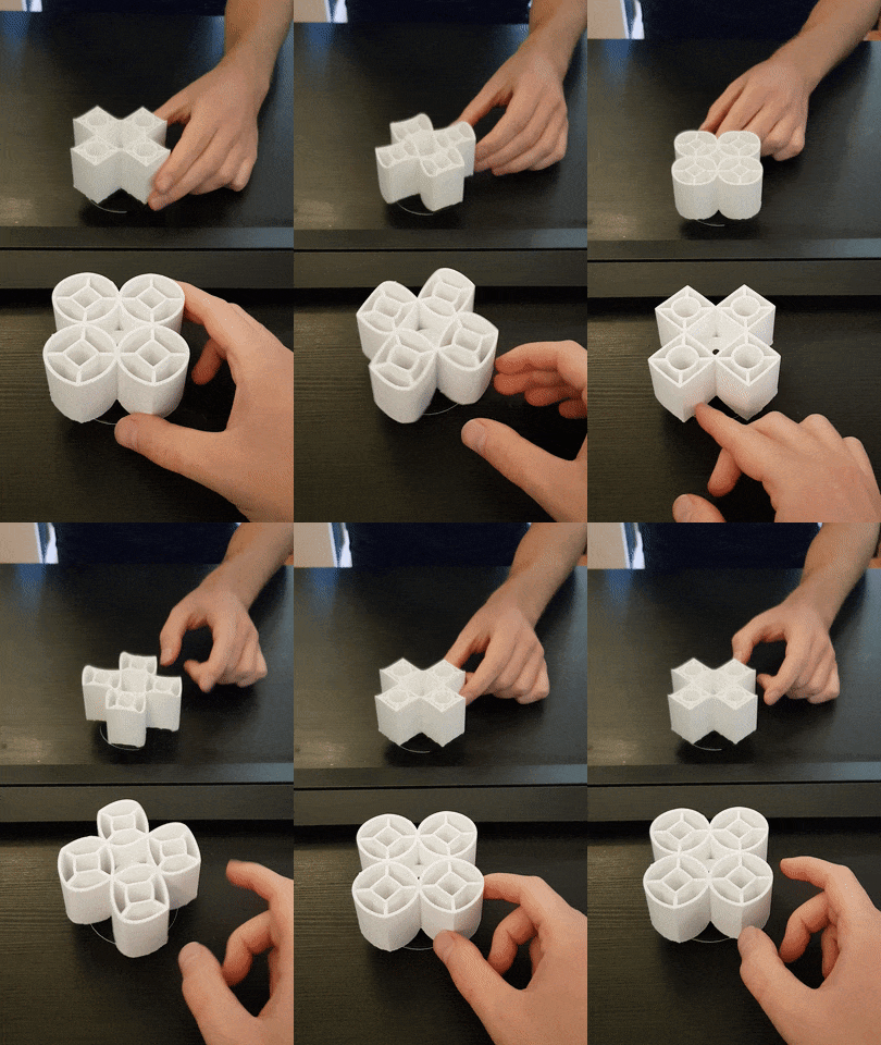
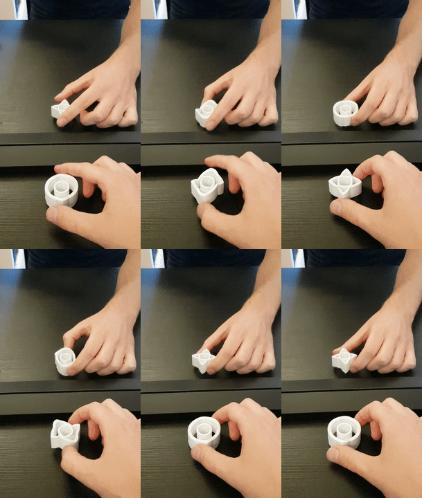
Based on the papers by Kokichi Sugihara, I have implemented the calculations to make various ambiguous cylinders. The end product is an exhibition for Bekk at Teknisk Museum in Oslo, with various figures 3D-printed.
--> View all and download the files on Thingiverse <--
To view all or get the files to print yourself, check the big link above the pictures. View the implementation here. (What this repo is about) Drag with mouse to look around. What you see is an object and the mirror reflection being something else. A circle from one direction, square from other.
src is a folder containing the web-app. Run with npm install and npm run watch from root.
The frontend does the calculations and allow easy visualization of the paths.
poster contains files and description (in Norwegian) for a poster to accompany the exhibition.
3dfiles contains the end result and vector files. svgshapes.ai contains the 2D shapes, that is then exported to SVG-strings for the webapp.
The various *.obj files are output from the webapp, giving the shapes needed for the illusions to work.
The obj files are then imported into Blender, and further edited. From there the shapes are exported as
*.stl files to be opened in Ultimaker Cura and printed.
Workflow
More for my own use, so I can remember...
Create SVG paths
I draw them in Illustrator using pen tool, from 0px to 100px. When happy, copy the path to clipboard.
Paste it into some texteditor. The SVG will contain a path element with a d attribute. Copy that into svgCalc.js to make us
of it as a function.
Calculate impossible shape
Make pairs of functions matching the wanted shapes from both viewing directions, ala
let circleSquare = [
    {func1: svgFuncBinary(svgHalfCircle), func2: svgFuncBinary(svgTriangle)},
    {func1: inverse(svgFuncBinary(svgHalfCircle)), func2: inverse(svgFuncBinary(svgTriangle))},
];
and pass it to the intersections-calculator. The resulting obj-file
is also made, fetch it from console by typing copy(window.objFile) and paste it into a text editor.
Edit file in Blender
Import the obj file, select Object -> Transform -> Geometry to Origin to get it somewhere visible.
Scale it S to 0.2 or so that it's approx 4units = 4cms wide. Apply the scale, ctrl + a. Height approx 5 units.
If the object contains several paths, they may need to be connected or split.
To split, go into edit mode, select a vertex, press L to select all linked, and then P to separate.
To join, select two vertices to join and press F.
Alt 1
Next step is to transform the shape into something with width and mass. Convert it into a curve using alt + C.
Add a bevel object, a line going from (-0.5,0.5) in Y. This should add a shape to the curve. Change value of Twisting to
something that looks good. May have to select Minimum and manually twist vertices using Ctrl + T.
Select the shape again in object mode and press alt + C to convert it back to a mesh, now being more than a thin line.
Alt
Go into edit mode. Select all vertices and extrude E. Press Esc. Can then either scale S to 0.8, shrinken alt+S to -0.4, or
scale twice for only x and y. See what looks best.
Next, we should make it solid. First way is to make it like a cylinder. Select all vertices, extrude E, and move the new
vertices in the Z direction to get the proper height. Press S, Z, 0 to scale the vertices to same height to get a flat base.
Other way is to fill in the top. Again extrude, but scale S the new vertices into a small point in the middle, and then
select merge at center from the tool menu. Or select all vertices and press F to generate face, or Grid Fill.
In both cases, it can be nice to select all vertices and recalculate normals.
To make a support it can rotate on, make a cylinder that's 0.5cm diameter and put it through some part of the object.
Select the original object, then select Add modifier -> Boolean and select the cylinder. Select Difference to cut
a cylinder hole. If the modifier doesn't work, try to use Mesh -> Clean up -> Fill holes.
Then export as stl. Select only current object, and scale * 10
Printing
Enabling the experimental setting "adaptive layers" seems to work well. Can then print the cylinder lowres, and then shape-paths finer, without it taking forever.


