Azure-Samples / Iot Hub C M0wifi Getstartedkit
Programming Languages
Get Started with Microsoft Azure IoT Starter Kit - Adafruit Feather M0 WiFi (Arduino-compatible)
Note: this article has been archived and it is not longer updated. Instructions may not be totally up to date.
Looking for something simple? This tutorial is very complete and contains a lot of detail. If you want something quick and simple, try one of these:
This page contains technical information to help you get familiar with Azure IoT using the Azure IoT Starter Kit - Feather M0 WiFi (Arduino-compatible). You will find two tutorials that will walk you through different scenarios: the first tutorial will show you how to connect your Azure IoT Starter kit to our Remote Monitoring preconfigured solution from Azure IoT Suite. In the second tutorial, you will leverage Azure IoT services to create your own IoT architecture.
You can choose to start with whichever tutorial you want to. If you've never worked with Azure IoT services before, we encourage you to start with the Remote Monitoring solution tutorial, because all of the Azure services will be provisioned for you in a built-in preconfigured solution. Then you can explore how each of the services work by going through the second tutorial.
We hope you enjoy the process. Please provide feedback if there's anything that we can improve.
Don't have a kit yet?: Click here
- Running a Simple Remote Monitoring Solution on Feather M0 WiFi
- Using Microsoft Azure IoT Services to Identify Temperature Anomalies
Running a Simple Remote Monitoring Solution on Feather M0 WiFi (Arduino-compatible)
This tutorial describes the process of taking your Feather M0 WiFi kit, and using it to develop a temperature, humidity and pressure reader that can communicate with the cloud using the Microsoft Azure IoT SDK.
Table of Contents
- 1.1 Tutorial Overview
- 1.2 Before Starting
- 1.3 Create a New Azure IoT Suite Remote Monitoring solution and Add Device
- 1.4 Connect the BME280 Sensor Module to your Device
- 1.5 Add the Feather M0 WiFi to the Arduino IDE
- 1.6 Install Library Dependencies
- 1.7 Modify the Remote Monitoring Sample
- 1.8 Build Your Remote Monitoring Sample
- 1.9 View the Sensor Data from the Remote Monitoring Portal
- 1.10 Next steps
1.1 Tutorial Overview
In this tutorial, you'll be doing the following:
- Setting up your environment on Azure using the Microsoft Azure IoT Suite Remote Monitoring preconfgiured solution, getting a large portion of the set-up that would be required done in one step.
- Setting your device and sensors up so that it can communicate with both your computer, and Azure IoT.
- Updating the device code sample to include our connection data and send it to Azure IoT to be viewed remotely.
1.2 Before Starting
1.2.1 Required Software
- Arduino IDE, version 1.6.8. from www.arduino.cc (Earlier versions will not work with the AzureIoT library)
- Sensor interface library from Adafruit: https://github.com/adafruit/Adafruit_BME280_Library/archive/master.zip
1.2.2 Required Hardware
- Adafruit Feather M0 WiFi kit
- A microB USB cable
- A desktop or laptop computer which can run Arduino IDE 1.6.8
1.3 Create a New Azure IoT Suite Remote Monitoring solution and Add Device
- Log in to Azure IoT Suite with your Microsoft account and click Create a New Preconfigured Solution
Note: For first time users, click here to get your Azure free trial which gives you 200USD of credit to get started.
- Click select in the Remote Monitoring option
- Type in a solution name. For this tutorial we’ll be using “FeatherM0Suite” (You will have to name it something else. Make it unique. I.E. "ContosoSample")
Note: Make sure to copy down the names and connection strings mentioned into a text document for reference later.
- Choose your subscription and desired region to deploy, then click Create Solution
- Wait for Azure to finish provisioning your IoT suite (this process may take up to 10 minutes), and then click Launch
Note: You may be asked to log back in. This is to ensure your solution has proper permissions associated with your account.
- Open the link to your IoT Suite’s “Solution Dashboard.” You may have been redirected there already.
- This opens your personal remote monitoring site at the URL <Your Azure IoT Hub suite name>.azurewebsites.net (e.g. FeatherM0Suite.azurewebsites.net)
- Click Add a Device at the lower left hand corner of your screen
- Add a new custom device
- Enter your desired
device ID. In this case we’ll use “FeatherM0_w_BME280”, and then click Check ID - If Device ID is available, go ahead and click Create
- Make note of your
device ID,Device Key, andIoT Hub Hostnameto enter into the code you’ll run on your device later.
Warning: The Remote Monitoring solution provisions a set of Azure IoT Services in your Azure account. It is meant to reflect a real enterprise architecture and thus its Azure consumption is quite heavy. To avoid unnecessary Azure consumption, we recommend you delete the preconfigured solution in azureiotsuite.com once you are done with your work (since it is easy to recreate). Alternatively, if you want to keep it up and running you can do two things to reduce consumption:
-
Visit this guide to run the solution in demo mode and reduce the Azure consumption.
-
Disable the simulated devices created with the solution (Go to Devices>>Select the device>> on the device details menu on the right, clich on Disable Device. Repeat with all the simulated devices).
-
Stop your remote monitoring solution while you are working on the next steps. (See: Troubleshooting)
- For additional reference, refer to the following:
- https://azure.microsoft.com/en-us/documentation/articles/iot-suite-remote-monitoring-sample-walkthrough/
- https://azure.microsoft.com/en-us/documentation/articles/iot-suite-connecting-devices/
1.4 Connect the BME280 Sensor Module to your Device
- Using this image as a reference, connect your BME280 and Feather M0 WiFi to the breadboard
- All connections are on the board, not on the device
Note: Column on the left corresponds to the sensor and on the right to the board. On the image, the board is place between 10 and 30, with the RST pin connected to row 29, and sensor between 1 and 9, with the CS pin connected to the row 1. With this layout, you are able to connect wires next to the corresponding pins on the breadboard. Additionally, when counting the - and + pins, start from the right and count in, as these do not align with the numbers indicated on the board.
| Start | End | Cable Color |
|---|---|---|
| CS (Pin 1E) | CE0 (Pin 16B) | Orange cable |
| SDI (Pin 2E) | MO (Pin 18J) | Blue cable |
| SDO (Pin 3E) | MI (Pin 17J) | White cable |
| SCK (Pin 4E) | SCK (Pin 19J) | Yellow cable |
| GND (Pin 5E) | Pin 5- | Black cable |
| 3Vo (6E) | Pin 6+ | Red cable |
| Pin 21- | Pin 26J | Black cable |
| Pin 23+ | Pin 28J | Red cable |
| Start | End | Connector |
|---|---|---|
| B7 | B1 | BME280 |
- For more information regarding the sensor, see: Adafruit BME280 sensor setup
At the end of your work, your Feather M0 WiFi should be connected to the sensor. We'll test it in the next sections.
1.5 Add the Feather M0 WiFi to the Arduino IDE
You will need to install the Feather M0 WiFi board extension for the Arduino IDE. This takes two steps:
-
Follow the instructions here. There you will see how to add a URL pointing to Adafruit's repository of board extensions.
-
Then continue with Using Arduino IDE, and see how to make the Feather M0 WiFi board selectable under the Tools menu, and how to get the Blink sketch to run.
- If you have issues uploading to the Feather M0, click the RST button twice (double-click) to get back into the bootloader.
1.6 Install Library Dependencies
For this project, we'll need to install the following libraries using the Arduino IDE:
- Adafruit BME280
- Adafruit Unified Sensor
- RTCZero
- AzureIoTHub
- AzureIoTUtility
- AzureIoTProtocol_HTTP
- WiFi101
To install them, click on the Sketch -> Include Library -> Manage Libraries. Search for each library using the box in the upper-right to filter your search, click on the found library, and click the "Install" button.
Note: Starting on version 1.0.17, AzureIoTHub required the AzureIoTUtility and one of the available protocols. These samples use the AzureIoTProtocol_HTTP, but it is prepared to work with AzureIoTProtocol_MQTT too.
Note: Arduino version 1.8.3 with WiFi101 does not support SSL connections on ports other than 443, so the MQTT protocol fails to connect. After this issue has been fixed MQTT support will be available again.
Note: If you have an earlier version of the IoT library, navigate to your Arduino documents directory. Inside the "Libraries" folder, there will be a number of installed libraries. Simply delete the AzureIoT folder.
1.7 Modify the Remote Monitoring sample
- Unzip the example code, and double-click the file
remote_monitoring.inoto open the project in the Arduino IDE. - You will be prompted to create a folder. Do this, and move the other files in the folder into the newly created child folder
- In the project, edit the
iot_configs.h, look for the following lines of code:
#define IOT_CONFIG_WIFI_SSID            "<Your WiFi network SSID or name>"
#define IOT_CONFIG_WIFI_PASSWORD        "<Your WiFi network WPA password or WEP key>"
- Replace the placeholders with your WiFi name (SSID), WiFi password, and the device connection string you created at the beginning of this tutorial.
- Look for the following line of code and replace the placeholders connection information (this is the Device information that you obtained in the Remote Monitoring console):
#define IOT_CONFIG_CONNECTION_STRING "HostName=<host_name>.azure-devices.net;DeviceId=<device_id>;SharedAccessKey=<device_key>"
- Save with
Control-s
1.8 Build Your Remote Monitoring Sample
- Double-click the reset button (located by the USB input) on the Feather M0 WiFi to put it in boot-loader mode. The red LED will fade in and out to show bootload mode.
- On windows, the COM port will disconnect, and a new one will appear. Use Tools -> Port -> COM to re-select it.
- Build and upload the code using Sketch -> Upload.
Note: As of 1.6.8, the Arduino IDE doesn't properly show "Upload Completed", even when it succeeds.
- There should now be a green LED on your Feather M0 WiFi. Re-select the COM port if necessary, and then open the Serial Monitor. After 15 seconds you should see a measurements update.
Note: When first starting you will likely see a “Fetching NTP epoch time failed” error – This is normal, and it trying to sync with Azure. This can take even up to 30 seconds to find a NTP server to sync with. One it is synced, it should start transmitting from there.
1.9 View the Sensor Data from the Remote Monitoring Portal
- Once you have the sample running, visit your dashboard by visiting azureiotsuite.com and clicking “Launch” on your solution
- Make sure the “Device to View” in the upper right is set to your device
- If the demo is running, you should see the graph change as your data updates in real time!
Note: Make sure you delete or stop your remote monitoring solution once you have completed this to avoid unnecessary Azure consumption! (See: Troubleshooting)
1.10 Next steps
Please visit our Azure IoT Dev Center for more samples and documentation on Azure IoT.
Using Microsoft Azure IoT Services to Identify Temperature Anomalies
This tutorial describes the process of taking your Microsoft Azure IoT Starter Kit for the Feather M0 WiFi, and using it to develop a temperature and humidity reader that can communicate with the cloud using the Microsoft Azure IoT SDK.
Table of Contents
- 2.1 Tutorial Overview
- 2.2 Before Starting
- 2.3 Connect the Sensor Module to your Device
- 2.4 Create a New Microsoft Azure IoT Hub and Add Device
- 2.5 Create an Event Hub
- 2.6 Create a Storage Account for Table Storage
- 2.7 Create a Stream Analytics job to Save IoT Data in Table Storage and Raise Alerts
- 2.8 Node Application Setup
- 2.9 Add the Feather M0 WiFi to the Arduino IDE
- 2.10 Install Library Dependencies
- 2.11 Modify the Command Center Sample
- 2.12 Build Your Command Center Sample
- 2.13 Next steps
2.1 Tutorial Overview
This tutorial has the following steps:
- Provision an IoT Hub instance on Microsoft Azure and adding your device.
- Prepare the device, get connected to the device, and set it up so that it can read sensor data.
- Configure your Microsoft Azure IoT services by adding Event Hub, Storage Account, and Stream Analytics resources.
- Prepare your local web solution for monitoring and sending commands to your device.
- Update the sample code to respond to commands and include the data from our sensors, sending it to Microsoft Azure to be viewed remotely.
Here is a breakdown of the data flow:
- The application running on the Adafruit Feather M0 WiFi will get temperature data from the temperature sensor and it will send them to the IoT Hub
- A Stream Analytics job will read the data from IoT Hub and write them to an Azure Storage Table. Also, if an anomaly is detected, then this job will write data to an Event Hub
- The Node.js application that is running on your computers will read the data from the Azure Storage Table and the Event Hub and will present them to the user
The end result will be a functional command center where you can view the history of your device's sensor data, a history of alerts, and send commands back to the device.
2.2 Before Starting
2.2.1 Required Software
- Git - For cloning the required repositories
- Node.js - For the Node application, we will go over this later.
- Arduino IDE, version 1.6.8. (Earlier versions will not work with the Azure IoT library)
- Sensor interface library from Adafruit. https://github.com/adafruit/Adafruit_BME280_Library/archive/master.zip
2.2.2 Required Hardware
- Adafruit Feather M0 WiFi IoT kit
- A microB USB cable
- A desktop or laptop computer which can run Arduino IDE 1.6.8
2.3 Connect the Sensor Module to your Device
- Using this image as a reference, connect your BME280 and Feather M0 WiFi to the breadboard
- All connections are on the board, not on the device
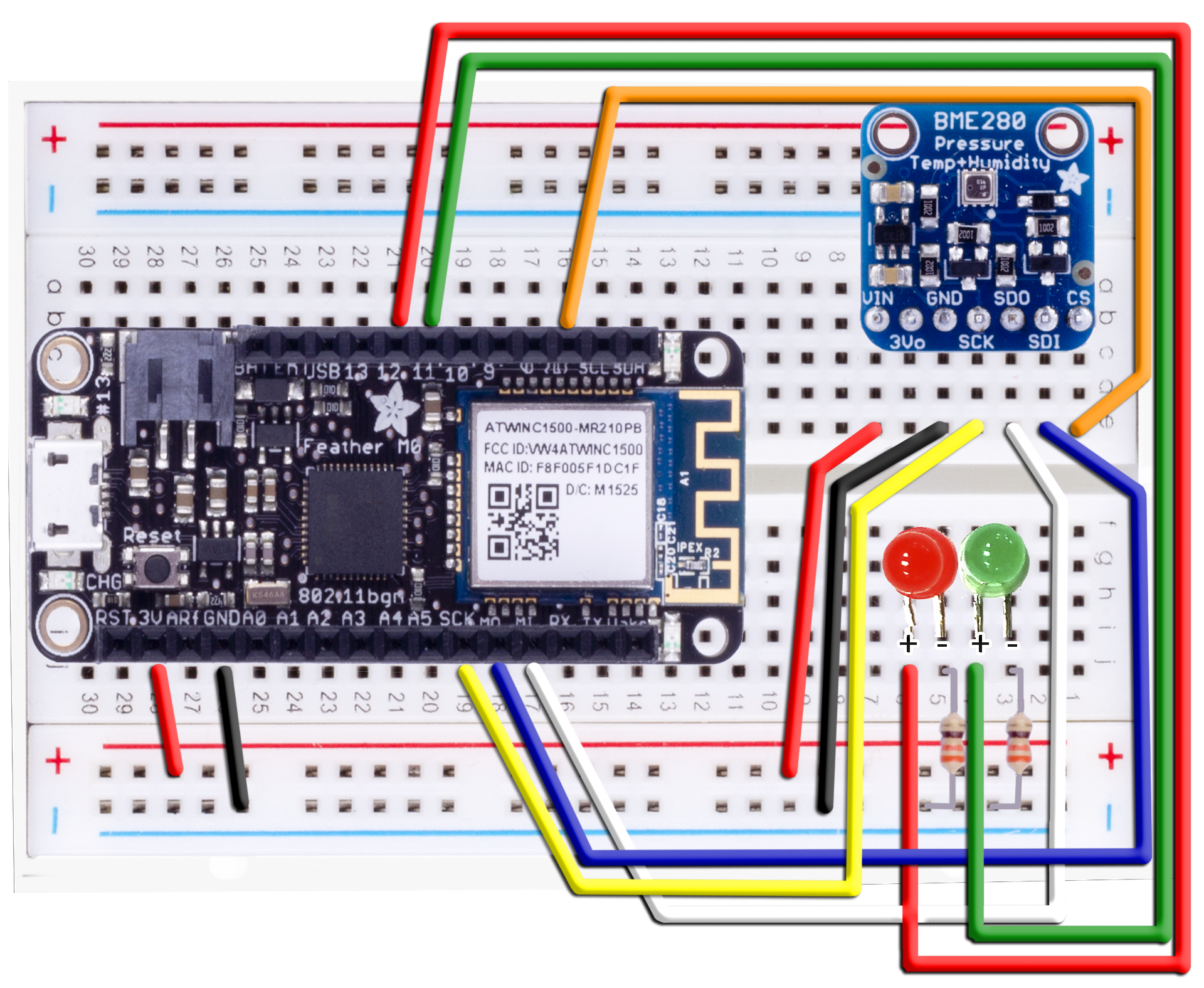
Note: Column on the left corresponds to the sensor and on the right to the board. On the image, the board is place between 10 and 30, with the RST pin connected to row 29, and sensor between 1 and 9, with the CS pin connected to the row 1. With this layout, you are able to connect wires next to the corresponding pins on the breadboard. Additionally, when counting the - and + pins, start from the right and count in, as these do not align with the numbers indicated on the board.
Note: The resistor can change a little from one kit to another, e.g. it can be 330 Ohm (orange, orange, brown) or 560 Ohm (green, blue, brown). Both will work with success.
| Start | End | Cable Color |
|---|---|---|
| CS (Pin 1E) | Pin 16B | Orange cable |
| SDI (Pin 2E) | MO (Pin 18J) | Blue cable |
| SDO (Pin 3E) | MI (Pin 17J) | White cable |
| SCK (Pin 4E) | SCK (Pin 19J) | Yellow cable |
| GND (Pin 5E) | Pin 7- | Black cable |
| GND (Pin 26J) | Pin 21- | Black cable |
| 3Vo (Pin 6E) | Pin 8+ | Red cable |
| 3V (Pin 28J) | Pin 23+ | Red cable |
| Start | End | Connector |
|---|---|---|
| B7 | B1 | BME280 |
| 3I | 4I | Green LED |
| 5I | 6I | Red LED |
| Pin 6J (long LED leg) | Pin 21B | Red cable |
| Pin 4J (long LED leg) | Pin 20B | Green cable |
| Pin 3J | Pin 3- | 330 Ohm |
| Pin 5J | Pin 5- | 330 Ohm |
- For more information, see: Adafruit BME280 sensor setup
- For more information regarding LEDs, see the following article: [Light-emitting Diodes]
At the end of your work, your Feather M0 WiFi should be connected with a working sensor. We'll test it in the next sections.
2.4 Create a New Microsoft Azure IoT Hub and Add Device
- To create your Microsoft Azure IoT Hub and add a device, follow the instructions outlined in the Setup IoT Hub Microsoft Azure Iot SDK page.
- After creating your device, make note of your connection string to enter into the code you’ll run on your device later
Note: Make sure to copy down the names and connection strings mentioned into a text document for reference later.
2.5 Create an Event Hub
Event Hub is an Azure IoT publish-subscribe service that can ingest millions of events per second and stream them into multiple applications, services or devices.
- Log on to the Microsoft Azure Portal
- Click on New -> Internet of Things-> Event Hub
- Enter the following settings for the Event Hub Namespace (use a name of your choice for the event hub and the namespace):
- Name:
Your choice(we choseFeather2Suite) - Pricing Tier:
Basic - Subscription:
Your choice - Resource Group:
Your choice - Location:
Your choice
- Name:
- Click on Create
- Wait until the Event Hub Namespace is created, and then create an Event Hub using the following steps:
- Click on your
Feather2SuiteEvent Hub Namespace (or pick any other name that you used) - Click the Add Event Hub
- Name:
featherEventHub
- Click on your
- Click on Create
- Wait until the new Event Bus is created
- Click on the Event Hubs arrow in the Overview tab (might require a few clicks, until the UI is updated)
- Select the
featherEventHubeventhub and go in the Configure tab in the Shared Access Policies section, add a new policy:- Name =
readwrite - Permissions =
Send, Listen
- Name =
- Click Save at the bottom of the page, then click the Dashboard tab near the top and click on Connection Information at the bottom
- Copy down the connection string for the
readwritepolicy you created. - From the your IoT Hub Settings (The Resource that has connected dots) on the Microsoft Azure Portal, click the Messaging blade (found in your settings), write down the Event Hub-compatible name
- Look at the Event-hub-compatible Endpoint, and write down this part: sb://thispart.servicebus.windows.net/ we will call this one the IoTHub EventHub-compatible namespace
2.6 Create a Storage Account for Table Storage
Now we will create a service to store our data in the cloud.
- Log on to the Microsoft Azure Portal
- In the menu, click New and select Data + Storage then Storage Account
- Name:
Your choice(we chosefeatherstorage) - Deployment model:
Classic - Performance:
Standard - Replication:
Read-access geo-redundant storage (RA-GRS) - Subscription:
Your choice - Resource Group:
Your choice - Location:
Your choice
- Name:
- Once the account is created, find it in the resources blade or click on the pinned tile, go to Settings, Keys, and write down the primary connection string.
2.7 Create a Stream Analytics job to Save IoT Data in Table Storage and Raise Alerts
Stream Analytics is an Azure IoT service that streams and analyzes data in the cloud. We'll use it to process data coming from your device.
-
Log on to the Microsoft Azure Portal
-
In the menu, click New, then click Internet of Things, and then click Stream Analytics Job
-
Enter a name for the job (We chose “FeatherStorageJob”), a preferred region, then choose your subscription. At this stage you are also offered to create a new or to use an existing resource group. Choose the resource group you created earlier.
-
Once the job is created, open your Job’s blade or click on the pinned tile, and find the section titled “Job Topology” and click the Inputs tile. In the Inputs blade, click on Add
-
Enter the following settings:
- Input Alias =
TempSensors - Source Type =
Data Stream - Source =
IoT Hub - IoT Hub =
Feather2Suite(use the name for the IoT Hub you create before) - Shared Access Policy Name =
iothubowner - Shared Access Policy Key = The
iothubownerprimary key can be found in your IoT Hub Settings -> Shared access policies - IoT Hub Consumer Group = "" (leave it to the default empty value)
- Event serialization format =
JSON - Encoding =
UTF-8
- Input Alias =
-
Back to the Stream Analytics Job blade, click on the Query tile (next to the Inputs tile). In the Query settings blade, type in the below query and click Save:
SELECT
    DeviceId,
    EventTime,
    MTemperature as TemperatureReading
INTO
    TemperatureTableStorage
from TempSensors
WHERE
   DeviceId is not null
   and EventTime is not null

SELECT
    DeviceId,
    EventTime,
    MTemperature as TemperatureReading
INTO
    TemperatureAlertToEventHub
FROM
    TempSensors
WHERE MTemperature>25
Note: You can change the 25 to 0 when you're ready to generate alerts to look at. This number represents the temperature in degrees celsius to check for when creating alerts. 25 degrees celsius is 77 degrees fahrenheit.
- Back to the Stream Analytics Job blade, click on the Outputs tile and in the Outputs blade, click on Add
- Enter the following settings then click on Create:
- Output Alias =
TemperatureTableStorage - Sink =
Table Storage - Subscription =
Provide table settings storage manually - Storage account =
featherstorage(The storage account you created earlier) - Storage account key = (The primary key for the storage account made earlier, can be found in Settings -> Keys -> Primary Access Key)
- Table Name =
TemperatureRecords(Your choice - If the table doesn’t already exist, Local Storage will create it) - Partition Key =
DeviceId - Row Key =
EventTime - Batch size =
1
- Output Alias =
- Back to the Stream Analytics Job blade, click on the Outputs tile, and in the Outputs blade, click on Add
- Enter the following settings then click on Create:
- Output Alias =
TemperatureAlertToEventHub - Sink =
Event Hub - Subscription =
Provide table settings storage manually - Service Bus Namespace =
Feather2Suite - Event Hub Name =
feathereventhub(The Event Hub you made earlier) - Event Hub Policy Name =
readwrite - Event Hub Policy Key =
Primary Key for readwrite Policy name(That's the one you wrote down after creating the event hub) - Partition Key Column =
0 - Event Serialization format =
JSON - Encoding =
UTF-8 - Format =
Line separated
- Output Alias =
- Back in the** Stream Analytics blade**, start the job by clicking on the **Start **button at the top
Note: Make sure to stop your Command Center jobs once you have when you take a break or finish to avoid unnecessary Azure consumption! (See: Troubleshooting)
2.8 Node Application Setup
- If you do not have it already, install Node.js and NPM.
- Windows and Mac installers can be found here: https://nodejs.org/en/download/
- Ensure that you select the options to install NPM and add to your PATH.
- Linux users can use the commands:
- Windows and Mac installers can be found here: https://nodejs.org/en/download/
sudo apt-get update
sudo apt-get install nodejs
sudo apt-get install npm
- Additionally, make sure you have cloned the project repository locally by issuing the following command in your desired directory:
git clone https://github.com/Azure-Samples/iot-hub-c-m0wifi-getstartedkit.git
- Open the
command_center_nodefolder in your command prompt (cd <path to locally cloned repro>/command_center_node) and install the required modules by running the following:
npm install -g bower
npm install
bower install
-
Open the
config.jsonfile and replace the information with your project. See the following for instructions on how to retrieve those values.- eventhubName:
- Open the Classic Azure Management Portal
- Open the Service Bus namespace you created earlier
- Switch to the EVENT HUBS page
- You can see and copy the name of your event hub from that page
- ehConnString:
- Click on the name of the event hub from above to open it
- Click on the "CONNECTION INFORMATION" button along the bottom.
- From there, click the button to copy the readwrite shared access policy connection string.
- deviceConnString:
- Use the information on the Manage IoT Hub to retrieve your device connection string using either the Device Explorer or iothub-explorer tools.
- iotHubConnString:
- In the Azure Portal
- Open the IoT Hub you created previously.
- Open the "Settings" blade
- Click on the "Shared access policies" setting
- Click on the "service" policy
- Copy the primary connection string for the policy
- storageAccountName:
- In the Azure Portal
- Open the classic Storage Account you created previously to copy its name
- storageAccountKey:
- Click on the name of the storage account above to open it
- Click the "Settings" button to open the Settings blade
- Click on the "Keys" setting
- Click the button next to the "PRIMARY ACCESS KEY" top copy it
- storageTableName:
- This must match the name of the table that was used in the Stream Analytics table storage output above.
- If you used the instructions above, you would have named it
TemperatureRecords - If you named it something else, enter the name you used instead.
- eventhubName:
{
    "port": "3000",
    "eventHubName": "event-hub-name",
    "ehConnString": "Endpoint=sb://name.servicebus.windows.net/;SharedAccessKeyName=readwrite;SharedAccessKey=aaaaaaaaaaaaaaaaaaaaaaaaaaaaaaaaaaaaaaaaaaa=",
    "deviceConnString": "HostName=name.azure-devices.net;DeviceId=device-id;SharedAccessKey=aaaaaaaaaaaaaaaaaaaaaa=="
    "iotHubConnString": "HostName=iot-hub-name.azure-devices.net;SharedAccessKeyName=service;SharedAccessKey=aaaaaaaaaaaaaaaaaaaaaaaaaaaaaaaaaaaaaaaaaaa=",
    "storageAcountName": "aaaaaaaaaaa",
    "storageAccountKey": "aaaaaaaaaaaaaaaaaaaaaaaaaaaaaaaaaaaaaaaaaaaaaaaaaaaaaaaaaaaaaaaaaaaaaaaaaaaaaaaaaaaaaa==",
    "storageTable": "TemperatureRecords"
}
- Now it is time to run it! Enter the following command:
node server.js
- You should then see something similar to:
app running on http://localhost:3000
client connected
- Visit the url in your browser and you will see the Node app running!
To deploy this project to the cloud using Azure, you can reference Creating a Node.js web app in Azure App Service.
Next, we will update your device so that it can interact with all the things you just created.
2.9 Add the Feather M0 WiFi to the Arduino IDE
You will need to install the Feather M0 WiFi board extension for the Arduino IDE. This takes two steps:
-
Follow the instructions here. There you will see how to add a URL pointing to Adafruit's repository of board extensions.
-
Then continue with Using Arduino IDE, and see how to make the Feather M0 WiFi board selectable under the Tools menu, and how to get the Blink sketch to run.
2.10 Install Library Dependencies
For this project, we'll need to install the following libraries using the Arduino IDE:
- Adafruit BME280
- RTCZero
- AzureIoTHub
- AzureIoTUtility
- AzureIoTProtocol_MQTT
To install them, click on the Sketch -> Include Library -> Manage Libraries. Search for each library using the box in the upper-right to filter your search, click on the found library, and click the "Install" button.
We'll also need to manually install the following libraries:
Instructions for manually installing a library can be found here.
Note: If you have an earlier version of the IoT library, navigate to your Arduino documents directory. Inside the "Libraries" folder, there will be a number of installed libraries. Simply delete the AzureIoT folder.
2.11 Modify the Command Center sample
- Unzip the example code, and double-click the file
command_center.inoto open the project in the Arduino IDE. - You will be prompted to creat a folder. Do this, and move the other files in the folder into the newly created child folder
- Look for the following lines of code:
static const char ssid[] = "[Your WiFi network SSID or name]";
static const char pass[] = "[Your WiFi network WPA password or WEP key]";
static const char* connectionString = "[Device Connection String]";
-
Replace the placeholders with your WiFi name (SSID), WiFi password, and the device connection string you created at the beginning of this tutorial.
-
Save with
Control-s -
In the same project, click on the
rem_ctrl.ctab to see that file. -
Look for the following lines of code:
static const char DeviceId[] = "[Device Name]";
- Replace the placeholders with your Device ID you created at the beginning of this tutorial.
- Save with
Control-s
2.12 Build Your Command Center Sample
- Double-click the reset button on the Feather M0 WiFi to put it in boot-loader mode. The red LED will fade in and out to show bootload mode.
- On Windows, the COM port will disconnect, and a new one will appear. Use Tools -> Port -> COM to re-select it.
- Build and upload the code using Sketch -> Upload.
Note: As of 1.6.8, the Arduino IDE doesn't properly show "Upload Completed", even when it succeeds.
- There should now be a green LED on your Feather M0 WiFi. Re-select the COM port if necessary, and then open the Serial Monitor. After 15 seconds you should see a measurements update.
- Data is now being sent off at regular intervals to Microsoft Azure. When it detects something out of range, you will see the LED you’ve set up turn from green to red!
- You can click the green button (labeled "Turn on") and the red button (labeled "Turn off") in the application to toggle the green and red LEDs in your kit.
Head back to your Node application and you will have a fully functional command center, complete with a history of sensor data, alerts that display when the temperature got outside a certain range, and commands that you can send to your device remotely.
Note: Make sure to stop your Command Center jobs once you have when you finish to avoid unnecessary Azure consumption! (See: Troubleshooting)
2.13 Next steps
Please visit our Azure IoT Dev Center for more samples and documentation on Azure IoT.
Troubleshooting
Stopping Provisioned Services
- In the Microsoft Azure Portal
- Click on "All Resources"
- For each Stream Analytics and Web App resource:
- Click on the resource and click the "Stop" button in the new blade that appears
- For each IoT Hub resource:
- Click on the resource and click the "Devices" button in the new blade that appears
- Click on each device in the list and click the "Disable" button that appears in the new blade at the bottom
Data is not showing up in the Node.js application
In this section we will explain how to see the data flowing from the Arduino application to the Node.js application:
- Arduino application: In the Arduino IDE go to Tools -> Serial Monitor
- IoT Hub: Use Device Explorer
- Azure Storage Table: Use Azure Storage Explorer