joshsanz / Pov_display
Labels
Projects that are alternatives of or similar to Pov display
Arduino Based Persistence of Vision Display
##Meghan Jimenez and Josh Sanz ###Built for E190p Embedded Systems
Introduction
The goal of this project is to create a persistence of vision (POV) display, that is, a display that relies on the latency of human vision to create more interesting images than a static display can deliver. The inspiration for this project comes from the art piece Full Turn. This piece takes two LCD screens placed back-to-back and spins them at high speeds. Since this piece utilizes POV and the resolution of these displays is high, very interesting and complex shapes can be displayed. The images created can even look three dimensional.
Since Full Turn is an art piece rather than an engineering project, finding technical specifications on the display proved impossible and the expense of using two large LCD screens is difficult to surmount for someone who just wants to tinker. We created this tutorial to explain how to make a POV display similar to Full Turn with technical specifications and without the high cost.
Materials
Here is a list of items that we used for this project:
| Item | Cost | Supplier | Link |
|---|---|---|---|
| Arduino DUE* | $50 | Adafruit | http://www.adafruit.com/products/1076 |
| LED array | $40 now, $75 when we bought it | Adafruit | http://www.adafruit.com/products/1484 |
| 6-wire slip ring | $17.50 | Adafruit | http://www.adafruit.com/products/736 |
| Power supply (19 V, 3.3A) | $8.00 | Amazon | http://www.amazon.com/Laptop-Notebook-Adapter-Supply-Aspire/dp/B004FLR2EW/ref=sr_1_2?ie=UTF8&qid=1393394428&sr=8-2&keywords=laptop+power+supply |
| Motor (RS-385SH Mabuchi)* | -- | Stockroom | -- |
| Photoresistor | $1.50 | Sparkfun | https://www.sparkfun.com/products/9088 |
*We don’t necessarily recommend all of these items! It works with this setup, but there are a few things that we would change given the chance, so don’t go buying everything yet!
In addition to the pieces listed above we also used various odds and ends from our stockroom and machine shop:
- LM317 adjustable voltage regulators
- 1K potentiometer
- Wire
- Scrap wood
- Scrap sheet metal
- Wood screws
- Epoxy
- Hand drill/drill press
- Jointer
- Mill
- Bandsaw
- Sheet metal bender
The first thing to note is that this project might work just as well with an Arduino Uno. The DUE’s advantage is a faster clock speed and more pins if you want to connect other devices to the same board. From reviews that we read on Sparkfun, 16 MHz seems to be the minimum clock speed required to drive the LEDs which is exactly what the Uno runs at. We had a DUE on hand, so we used that. We also tried this with a Raspberry Pi and found that the timing was not precise enough for use with this array. Unless you want to put in significant work to try to make the timing better, we suggest not using a Raspberry Pi for this project.
Second, we had some issues with our motor choice. We tried several different motors before deciding that they were all far too small to drive our final frame. The motor listed in the table above works but it also gets hot and cannot run for too long. We had similar issues with the voltage regulators - this array pulls a lot of power and even with a large heat sink attached, the regulators began to heat up very quickly. We would recommend using a larger motor and better voltage regulators if possible.
Finally, remember that using these items was the easiest way for us to go about completing this project but there are definitely alternatives if you don’t have access to all of these things!
####Methods
-
Using the LED Array The LED array contains 32323=3072 separate LEDs. This is way too many to drive all at once, so it uses 12 LED drivers, each capable of controlling 16 LEDs at once, for a total of 192 LEDs driven at a time - exactly enough for two rows of the display. Four address bits are used to control which pair of rows is being driven at any given time. The LED drivers take in a clock signal, which is used to clock in the 32 columns of each row (the two signals for each rgb color account for the total of 192 LEDs). After an entire row has been clocked in, the display is disabled, a latch signal is toggled on and off again, and the row address is set. The display is then enabled and the chosen row of LEDs is driven. In order to give the impression of an entire display being on, the rows are cycled through very quickly, hence the minimum processor clock speed of 16 MHz. Sample code can be found in our github repo, or here. The Adafruit website has instructions for wiring the display to an Arduino here.
-
Building the Frame The first step to building the frame is finding a way to stabilize the LED array. We chose to do this by milling slots that are the width of the array down the center of two pieces of wood cut to the same length as the array. We then epoxied the top of the array into one piece of wood and the bottom into the other (Figure 1). The slotted piece of wood that is epoxied to the top of the array should also have a hole dead center that is slightly larger than the shaft of the motor that you plan to use. Be careful to place the hole in the center of the piece of wood at the center of the array as well! Once both pieces are attached, really try to make sure that your LED array is vertically straight! You can fix it later (like we did), but it’s easier if you get it right the first time.

The next step is to build the rotating base for the array to sit on. A hole the size of the larger end of the slip ring should be bored out of a piece of wood thick enough that the slip ring can fit completely inside the bored out hole. A hole should also be drilled through the side of the same piece to allow the wires to be accessed more easily. Place the larger end of the slip ring into the large hole and run the wires out through the smaller hole. The flat, black disk should sit directly on top of the wood. Epoxy this in place. Be careful not to get any epoxy into a place that could keep the slip ring from turning!
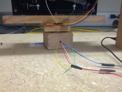
Then, take a smaller piece of wood and drill a hole slightly larger than the size of the smaller end of the slip ring. Chisel a channel out from the center hole to the edge of the piece of wood. Slide this over the smaller end of the slip ring, pulling the wires through the hole and down the channel. Epoxy the piece of wood to the small end of the slip ring being careful not to get any epoxy into a place that could keep the slip ring from turning. The result should like something like Figure 2.

Once the epoxy has dried completely, you can attach the two parts of the frame that you have made so far. The result should look something like Figure 3. The lower slotted piece of wood attached to the LED array should be epoxied directly onto the smaller piece of the spinning base. The wires should come out between the two pieces of wood using the channel you created. As you can see in Figure 3, our display also has two small wooden shims between the two parts of the base. This was to fix a forward tilt we saw in our array after epoxying it into the two slotted pieces of wood.
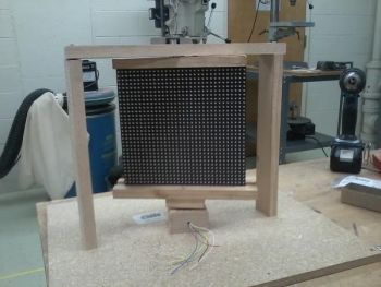
Next, you’ll need to put it all together with a motor base. Take a piece of particle board (or any other heavy material) and create a wooden frame that is both tall enough and wide enough for your LED array to spin in. This should look like Figure 4.
Once you have done this you need to find the place where the array spins under the top piece of wood the most easily. Our array is very close to the top bar because of the short shaft of the motor and it took a bit of sanding and careful placement to get something that would spin well. After identifying the best spot, screw the piece with the slip ring in it into place through the particle board.
Finally, the motor needs to be attached to the array and frame. We used a piece of sheet metal bent around the motor and screwed into the wood to hold up the motor and a small piece of wood with a tooth that fit into a space in the motor casing to keep the motor from spinning. The motor shaft was epoxied into the hole in the center of the top piece of slotted wood attached to the LED array. In the end, you should get something that looks like this:

If you’re having trouble getting this to spin well - sand it! We found that once it was assembled it was very easy to sand. We just put sandpaper between two rotating pieces that we thought should rotate better and spun the display until they rotated better! You can also try adding some grease to the area around the slip ring although we’re not sure how much this actually helped. In the end, your display should spin very easily. If it doesn’t, keep sanding! It’ll be easier on your motor!
-
The Light Sensor The light sensor is the easiest component to put together. We created a voltage divider from the 1k photoresistor in series with a TBD resistor. One side of the photoresistor is hook up to 5V. The junction between the two is hooked up to one of the slip ring wires and sent to an analog in pin on the Arduino, and the other side of the TBD resistor is sent to ground. We then read in the analog voltage from this circuit and used it to select the size of heart on the LED array. More light meant a bigger heart and less light would shrink the heart down to nothing.
-
Power If you don’t plan to have the POV display in an area with easy access to a DC power supply, you can use a laptop charger (which typically puts out 19.5V) and some voltage regulators to step down the voltage to a level safe for the Arduino and LED array. We used two LM317t adjustable power regulators to bring the voltage from the power supply down to 5V. They tend to get very hot and eventually internal thermal protection circuits shut them off, so we folded some sheet metal into a large heat sink which the wind from the spinning display cools. The LM317t’s require a reference voltage, which can be created using the circuit below (from the datasheet).

The Final Product
When everything is put together, the LED array should display a large heart with green and blue bars on either side. When the whole thing starts to spin the effect is quite impressive. The working POV display can be seen in this youtube video.