sim808gpstracker
DIY cheap GPS motorbike/car tracker based on ATMEGA 328P (arduino uno chip) and SIM808 module from China (includes GPS and GNSS function). The total cost is below 20USD ( as in 2019 ) and positioning accuracy is ~1-20 meters ( tested in Europe location). Accoriding to SIM7500 / SIM7600 modules (LTE CAT1 ) specification this source code also may work on these boards (except usage of GPRS connectivity ).
You can find SIMCOM modules guides here : https://simcom.ee/documents/
The device when called by mobile phone polls info from GPS module (if can fix to sattelites - tries several minutes to fix) or when not available polls cell-id info from nearest 2G cell and using GPRS query Google servers for GPS location of that 2G cell. Collected location information is send back as text message to your phone as Google Map link. I have tried to keep the code as simple as possible and conserve battery power so functionality is rather limited... However...
There is also experimental version "main7.c"/"main8.c" which uses set of commands to control behavior of the tracking device using text messages. One of modes (MULTI) sends 5 times GPS location in 4-5 minutes interval upon receiving particular message. There is also GUARD option to alert in case vehicle has been stolen and is on the move...
The software can also be further customized to provide location in realtime to some HTTP POST /FTP server (see my other IoT project where I am doing it with SIM800L module which has same commands : https://www.youtube.com/watch?v=i4JgbwCktYQ , the code is here https://github.com/mcore1976/smartmetering) - it is up to you to expand the code, it will take you probably few hours to implement this feature... But REMEMBER - Using GPRS to send HTTP / TCP IP requires good power source for SIM808 board otherwise it will restart itself with "UNDERVOLTAGE WARNING"...
BILL OF MATERIAL LIST (as for year 2019):
- SIM808 based board BK-SIM808 (10-12 USD on Aliexpress )
- search for "www.and-global.com" boards BK-SIM808 or equivalent (you may try here http://and-global.en.alibaba.com/ )... https://cdn.instructables.com/ORIG/FAO/80RU/IXLALERK/FAO80RUIXLALERK.pdf) it may also work with boards SKU405361-SIM808 (see description below for source code options)
-
GPS (passive) antenna with IPEX / U.FL connector matching BK-SIM808 board - 2 USD
-
GSM antenna with IPEX / U.FL connector matching BK-SIM808 board - 1 USD
-
ATMEGA 328P (arduino uno) - 2 USD or ATMEGA328P based board : https://www.theengineeringprojects.com/2018/06/introduction-to-arduino-pro-mini.html
-
XTAL 8MHz - quartz crystal with 8 MHz frequency to ensure clock stability of ATMEGA and keep it synchronized with serial port of SIM808 module even when temperature changes (internal RC oscillator in ATMEGA is very unstable). Using XTAL is optional (compile scripts configure internal RC clock by default ) but i do RECOMMEND using XTAL due to poor internal clock of ATMEGA. This one costs 0.2USD
-
2 x 22pF capacitor for XTAL - 0.2 USD
-
3x 1N4007 (1 USD) - to convert 5V from powerbank to 3.3V for ATMEGA328P VCC ( only for BK-808 board and others that require TTL 3.3V logic)
-
2x 1000uF / 16V capacitor ( 0.5 USD) - connect to VCC & GND of SIM808 board AND to existing 100uF (parallel) on the SIM808 board - usage of this capacitor depends on type of SIM808 board
-
100nF (or some other in range 100nF-1uF) / 12V (or higher) capacitor (0.2 USD) - connect to VCC & GND of ATMEGA328P ( if not using "Arduino Pro Mini" board)
-
universal PCB, pins & connector (2 USD) or some wires with pins if you going to use boards like "Arduino Pro Mini" instead
-
USB Powerbank 5V to make it work...
CONNECTIONS TO BE MADE :
- SIM808 board RXD (BK-SIM808 pin R) to ATMEGA328 TXD PIN #3,
- SIM808 board TXD (BK-SIM808 pin T) to ATMEGA328 RXD PIN #2
- SIM808 board DTR (BK-SIM808 pin S : SLEEP PIN) to ATMEGA328 PC5 PIN #28
- SIM808 board GND (BK-SIM808 pin G ) : to powerbank GND
- SIM808 board VCC (BK-SIM808 pin V / PWRIN ) : to powerbank +5V VCC
- SIM808 board PWRKEY (BK-SIM808 pin K - left unused - it is internally bound to GND, however when breaking this connection it can be used to switch on/off whole SIM808 board)
OPTIONAL) SIM808 RI/RING if available (No such pin on BK-SIM808 board) - to ATMEGA328P INT0 pin #4, and then you may experiment with ATMEGA POWERDOWN mode by uncommenting appropriate portion of the source code. I didn't have such board so I couldn't check this option.
-
Capacitor 1000uF between +5V and GND of powerbank (optional, most of them already has some huge capacitors)
-
put 3x 1N40007 diodes IN SERIAL between 5V VCC and ATMEGA328P VCC PIN #7 (only for BK808 board and others that use 3.3V TTL logic) - ATMEGA must be powered from ~3.3V to adopt TTL logic levels of outputs TXD/RXD of BK-SIM808 board
-
put 100nF capacitor between ATMEGA328P VCC pin #7 and ATMEGA328P GND pin #8 & PIN#22
-
connect GPS passive antenna and GSM antenna to appropriate IPEX / U.FL connectors of BK-SIM808 board. Probably it can work with active GPS antenna (but you would need to add another resistor for pullup antenna input to VCC - decribed here https://www.raviyp.com/embedded/205-sim808-gps-active-antenna-unable-to-acquire-fix-solution )
-
The AND-GLOBAL BK-SIM808 board I have used has TO SMALL electrolytic capacitor (mine had only 100uF). You have to solder/add another big capacitor (I have used 2200uF/10V, but it can be 1000uF/10V ) in parallel to make this board work correctly. Otherwise it will continously restart itself while trying to register to the 2G network.
-
Connect crystal 8MHz between pins 9 & 10 of ATMEGA 328p and add blocking capacitors 22pF between crystal pins and GND line. If you want to use crystal pleas modify "compileatmegaX" file by putting appropriate l-fuse value to avrdude command.
SOURCE FILE OPTIONS :
You can find several boards with SIM808 on the market. Some of them have full pinout like GND,RXD,TXD,DTR,RING - but others can have only serial port exposed : GND, RXD, TXD. Some boards are using 3.3V TTL logic on serial port, but others use 5V TTL logic. You have to pay attention to all the details and consult the seller before buying development board.
Below there are two types of source files provided, first for BK-808 board (with PIN DTR/SLEEP and RXD/TXD) and second file for any SIM808 based board with only RXD,TXD pins.
------ for BK808 board or other WITH DTR/SLEEP pin --------
"main.c" (+ compilation script "compileatmega" Linux /"compileatmega.bat" Windows) - source file for SIM808 boards WITH DTR/SLEEP PIN exposed as BK-808 board. To use this file you will have to attach ATMEGA PC5 PIN #28 to SIM808 board DTR/SLEEP pin.
"main7.c" (+ compilation script "compileatmega7" Linux/"compileatmega7.bat" Windows) - EXPERIMENTAL VERSION - source file for SIM808 boards WITH DTR/SLEEP PIN exposed as BK-808 board. To use this file you will have to attach ATMEGA PC5 PIN #28 to SIM808 board DTR/SLEEP pin.
This version provides SMS (mobile texting) control of tracker behavior :
Command can be send in lower or upper letters. If command is correct it will be responded with appropriate text message confirmation.
-
Command "ACTIVATE" stores the phone number of sender as allowed to MT call the device and get the current GPS/GSM position. Other calls will be ignored (security feature). Simply send a text message ACTIVATE to your simcard in GPS tracker to enable voice call answering with GPS position of the tracker to your phone number. This phone number will be stored in non volatile EPROM memory of ATMEGA328P chip so you need to send this command only once for your phonenumber. Only 1 phonenumber is stored and allowed to call.
-
Command "MULTI" gives CONTINOUS MODE of positioning and sends 5 times GPS location in 3-4 minutes interval. Simply send a text message MULTI to your simcard in GPS tracker to receive five GPS positions in 20 minutes sequence.
-
Command "SINGLE" gives single GPS/GSM positioning response. Simply send a text message SINGLE to your simcard in GPS tracker to receive single/current GPS position.
-
Command "GUARD" has been added to notify caller of GPS position change using text message (~300-500 meter sensivity is hardcoded but can be changed in the program). "GUARD MODE" can be stopped by sending "STOP" message at least once (getting out of this mode is confirmed by text message) or ends up automatically after first detection of movement.
------- for other boards ( that do not have neither RING nor DTR pin exposed ) ------
"main2.c" (+ compilation script "compileatmega2" Linux / "compileatmega2.bat" Windows)
- source file for SIM808 boards WIHOUT DTR/SLEEP PIN exposed. To use this file you DO NOT connect ATMEGA PC5 pin to DTR SIM808.
Example of board wihout SLEEP/DTR is this module SKU405361-SIM808 http://files.banggood.com/2016/06/SKU405361-SIM808.rar . These boards are also sold here : https://www.electrodragon.com/product/sim808-dev-board-gsmgprsgps-replacing-sim908/
Also pay attention to type of TTL logic the board uses. They have to match on both sides - ATMEGA328P and SIM808 board - otherwise you may kill the SIM808 board. If you want to use board that has 5V TTL logic DO NOT put 1N4007 Diodes to ATMEGA328P. If you want to use 3.3V TTL logic on SKU405361-SIM808 (old type), you will probably need to connect 3.3V from ATMEGA VCC (after 3x 1N4007 Diode drop it from 5V) to VMCU PIN (if available) of SIM808 board to switch it to 3.3V mode. You need to check all the details in SIM808 board manual.
"main8.c" (+ compilation script "compileatmega8" Linux / "compileatmega8.bat" Windows) - EXPERIMENTAL VERSION with SMS commands (as version 7) - source file for other SIM808 boards without DTR and RING pin. To use this source file only RXD, TXD, GND lines have to be connected from SIM808 board to ATMEGA 328P.
IMPORTANT !!! In the code you have to put correct APN, USERNAME and PASSWORD of GPRS access from your Mobile Network Operator before compiling - replace word "internet" with correct words for your MNO (check your with your mobile operator how to configure GPRS access) :
constchar SAPBR2[] PROGMEM = {"AT+SAPBR=3,1,"APN","internet"\r\n"}; // Put your mobile operator APN name here instead of 'internet'
constchar SAPBR3[] PROGMEM = {"AT+SAPBR=3,1,"USER","internet"\r\n"}; // Put your mobile operator APN username here instead of 'internet'
constchar SAPBR4[] PROGMEM = {"AT+SAPBR=3,1,"PWD","internet"\r\n"}; // Put your mobile operator APN password here instead of 'internet'
... otherwise you won't be able to receive GSM Cell location when vehicle is indoor (garage ?) !!! This is only needed if you want to have indoor position in case there is no satellite visibility.
COMPILATION ON LINUX PC :
Link to video how to program the chip : https://www.youtube.com/watch?v=7klgyNzZ2TI
To upload program code to the chip using cheapest USBASP programmer (less than 2 USD on eBay/Aliexpress) look at this page : http://www.learningaboutelectronics.com/Articles/Program-AVR-chip-using-a-USBASP-with-10-pin-cable.php
The script attached in repository ( "compileatmegaX") can be used to upload data to the chip if you have Linux machine with following packages : "gcc-avr", "binutils-avr" (or sometimes just "binutils"), "avr-libc", "avrdude" and optionally "gdb-avr"(debugger only if you really need it) . For example in Ubuntu download these packages using command : "sudo apt-get install gcc-avr binutils-avr avr-libc gdb-avr avrdude". After doing it you will be able to run compilation the script from the directory you have downloaded github files by commands:
- "sudo chmod +rx compiletmega*" and "sudo ./compileatmega7" ( for BK-808 board)
- "sudo chmod +rx compiletmega*" and "sudo ./compileatmega8" ( for other SIM808 boards )
COMPILATION ON WINDOWS 10 PC :
If you have Windows 10 machine - follow this tutorial to download and install full AVR-GCC environment : http://fab.cba.mit.edu/classes/863.16/doc/projects/ftsmin/windows_avr.html and use "compileatmegaXX.bat" files for compilaton in the directory where you have downloaded mainX.c files. You have to be logged as Windows Administrator and run "cmd" from search window to do that. Then use commands like "cd XXXXX" to change working directory to get to downloaded source files.
Some people do not like to use universal PCB and are having problems with soldering. You may use "Arduino Pro Mini" (or clone) instead. There are two types of this board - 5V voltage and 3.3V voltage. Pay attention to it when selecting the board so it will match SIM808 board TTL logic (3.3V - BK-808 or 5V like on other boards). In such case you will not need parts like XTAL and capacitors for ATMEGA, since they are already in place on such ARDUINO board.
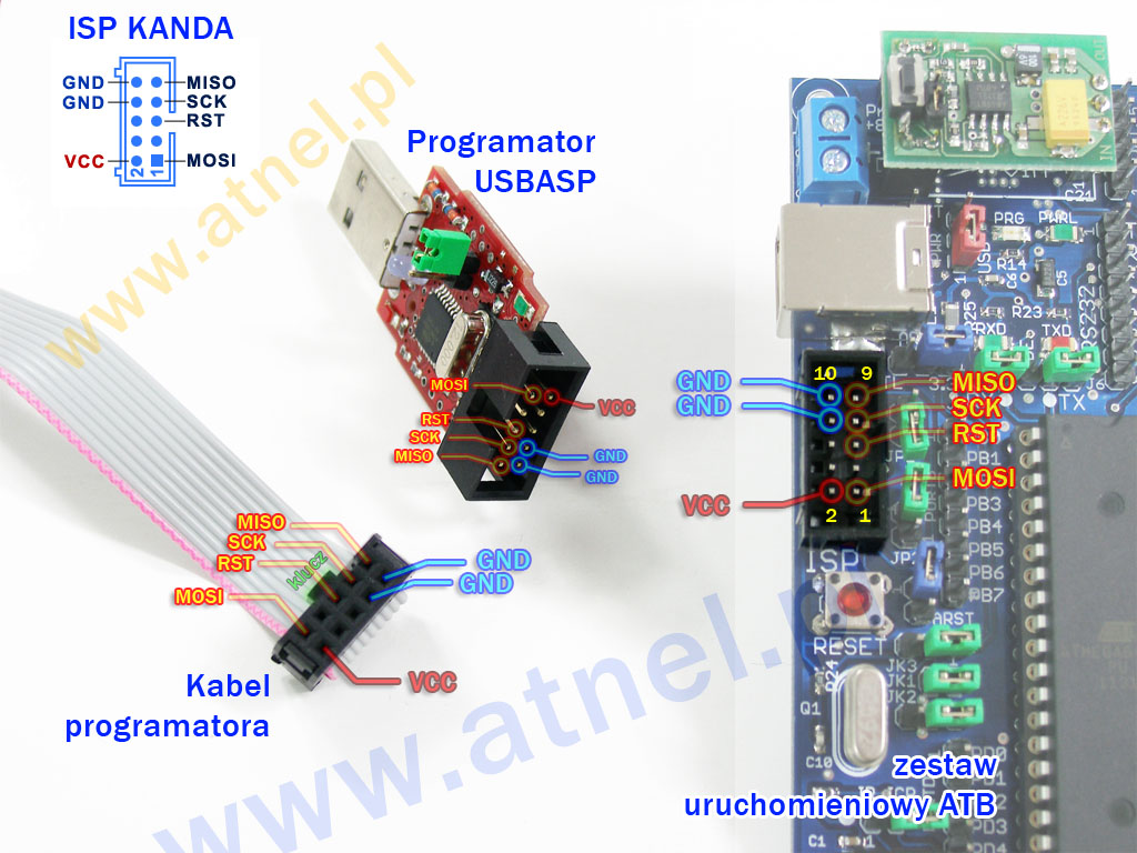
Even when using "Arduino Pro Mini" you will still have to connect USBASP programmer with KANDA socket (look here : https://www.atnel.pl/download/blog/ISP_KANDA.jpg ) to appropriate pins of this board : SCK (pin 13), MISO (pin 12), MOSI (pin 11), RESET (pin RST), pin VCC, pin GND and reprogram ATMEGA chip - like here when changing/uploading bootloader https://www.arduino.cc/en/Hacking/MiniBootloader Description of this board is here : https://www.theengineeringprojects.com/2018/06/introduction-to-arduino-pro-mini.html
Link to video how to program the chip : https://www.youtube.com/watch?v=7klgyNzZ2TI
NOTICE :
This GPS tracker solution is not based on ARDUINO FRAMEWORK (it does not use ARDUINO bootloader and we are getting rid of it here), it uses pure C code instead so USBASP programmer is still needed. It also utilizes hardware UART interface pins of ATMEGA that are normally used to program via ARDUINO framework... So USBASP programer is needed The code without ARDUINO framework takes less memory so it can be uploaded even to smaller/older/smaller chips like ATMEGA168 ( you can find cheaper Arduino Pro Mini board with ATMEGA168 for ~1,5USD).
OTHER INFO :
The solution has low power consumption because it is utilizing SLEEP MODE on SIM808 module (only on BK-808 board) and switches on GPS only when needed. I have found that on the board BK-SIM808 it is better to get rid of PWR LED (cut off) because it is taking few mA of current thus unnecessary increasing power consumption - keep that in mind. Generally speaking SIM808 board is not so power efficient as SIM800L because contains GPS/GNSS block.
The ATMEGA328P must be active all the time because my BK-SIM808 board does not have SIM808 RING/RI pin exposed (which can be used to wake up ATMEGA via hardware interrupt). In this design DTR pin of SIM808 module is used to sleepmode manipulation (when coming out of sleepmode the DTR pin must be held LOW for at least 50msec). Measured power consumption for whole gps tracker is 14mA when SIM808 is in sleepmode with PWR LED on, but by getting PWR LED out the current lowers to 8mA.
When SIM808 module sends SMS/GPRS data it it may draw a lot of current ( up to 2A ) in short peaks so it is crucial to use good cables and thick copper lines for GND and VCC on PCB. This is the main issue people face when dealing with SIMCOM modules. The voltage may additionaly drop during this situation so that is why such big capacitor is in use.
The tracker as designed will be powered from USB 5V Powerbank - it is good to use the cheapest USB powerbanks that do not have current sensor. Remember that GPS tracker will draw LOW current ( lower than 14mA). Some advanced powerbanks tend to switch off USB 5V when they find out that there is very little current consumed. If you have Powerbank with signalling LED then I suggest to get rid of this LED to reduce power drain on Powerbank. By adding LM1804/LM317/LM7805 circuit or DC-DC buck converter (LM2596) you may adopt design to power from +12V car battery.
You can see how it works here : https://www.youtube.com/watch?v=8R99t0O52GI&t=428s and here : https://www.youtube.com/watch?v=ZMRz5Emcvew