Tapuino-Reloaded
Designed in 2017 By @edu_arana in collaboration with @groovydrifter & @jgilcas. Based on the original schematic design of Peter Edwards.
Updates
20/01/2021: Uploaded gerbers version 0.42 with the pin8 fixed on HC4050.
20/01/2021: On rev 0.41 There might be a problem with pin 8 on the SD card buffer. If PCB manufacturer does not populate a required via to make pin 8 from the HC4050 to GND, this could produce a problem with SD card detection. If you have a multimeter, try to measure pin 8 from the HC4050 to GND, if you have continuity then the SD Card detection or initialization problem might be elsewhere, if not, to fix this, try to solder pin 8 to pin 2 of the octocoupler (GND). Find the instruction on how to fix this on the GERBERS-NANO directory. Thanks to the user Alleged-Geek for point this out.
12/11/2019: Updated license stuff (I usually not do this but I must start it with this).
12/11/2019: Released version 0.41 using Arduino Nano and 128x32 oled screen.
17/02/2018: Fixed a issue with the 2n2222. Not required anymore.
25/01/2018: New version has born :)
03/06/2017: Add DTR signal on the TTL programming port.
24/05/2017: If your Atmega328 is blank without bootloader you can take advantage by upload the bootloader and firmware directly to the atmega using an ISP like the USBASP. On the ISP folder there is a hex file that include the bootloader plus the firmware (tapuino) for oled screens.
License
Shield:
This work is licensed under a Creative Commons Attribution-ShareAlike 4.0 International License.

Note
This is a work in progress, several testing must be made but it should work as is. I take no responsibiltiy for any damage to any equipment that results from the use of this board. USE AT YOUR OWN RISK!
If you like the project or want to support it, you can buy me a beer or a KO-FI :)

Testers
Special thanks to:
@CommodoreSpain @thejanbeta @FREEZE64UK
For the awesome review of the Tapuino Reloaded.
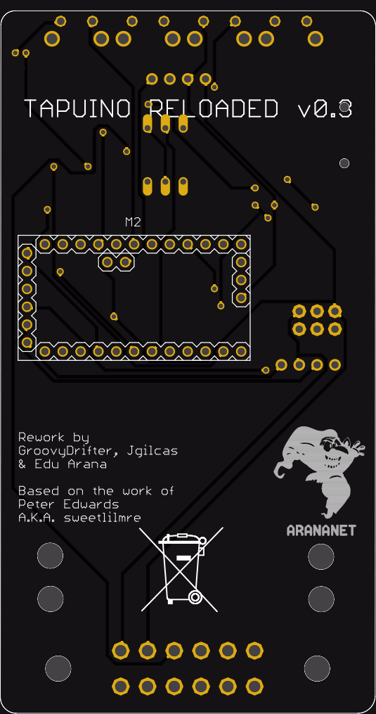
Version 0.42
Includes a reinforcement on the pin 8 of the 4050 buffer and another OLED position to use 0.96 128x64 oled display. The BOM is the same as the 0.41 version.

Version 0.41
This new version of the Tapuino-Reloaded uses a Arduino Nano instead of a PRO MINI like the ealier version. Now is more easy to flash and to update firmware since Ardunino Nano includes a in-build programmer. OLED Screen must be 128x32 and pinouts must be GND VCC SCL SDA (if ends with SDK needs a pullups). Added properly decoupling caps. Manually routed.
Images


Bill of materials
| Part | Value | Package |
|---|---|---|
| ABORT1 | Button | B3F-31XX |
| ACT | SMD led | CHIP-LED0805 |
| C1 | 100nf | 0805 |
| C2 | 100nf | 0805 |
| CON1 | CONECTOR_C64_DATASSETTE | CONECTOR_C64_DATASSETTE |
| IC1 | 4050D (HC4050 or HCT4050) | SO16 |
| M2 | ARDUINO-NANO | ARDUINO-NANO-3.0 |
| NEXT1 | Button | B3F-31XX |
| OK2 | 4N25M | DIL06 |
| OLED | Connector for Screen | 128x32 OLED SCREEN |
| POWER | SMD led | CHIP-LED0805 |
| PREV1 | Button | B3F-31XX |
| R5 | 330 | R0805 |
| R7 | 1k | R0805 |
| R9 | 1K | R0805 |
| SD1 | TF-HOLDER | TF-PULL |
| SELECT1 | Button | B3F-31XX |
#------------------------------------------------------------------------------------------------------------------------------------
Version 0.3
This new version include the footprint of the Arduino Pro Mini, so you just have to buy a module with compatible footprint and solder it on the PCB. Some of the components has been changed to a better position and some others has been replaced (please refer to the BOM). Remember, once you solder and flash the Tapuino, you just plug the Tapuino Reloaded on the back of your C64 (Breadbox & C) and that's it. This design also allows to use every type of i2c LCD or OLED Screen, by soldering a 1x4 row pin and taking out the lcd to a better viewable area, for example on computers like the Commodore PET.
Images

Instructions
The same as 0.2, except that you don't need to apply fuses on the Arduino Pro Mini.
Bill of materials
| Part | Value | Package |
|---|---|---|
| ABORT1 | Button | B3F-31XX |
| ACT | SMD led | CHIP-LED0805 |
| C3 | 22UF | 0805 |
| C4 | 22UF | 0805 |
| CON1 | CONECTOR_C64_DATASSETTE | CONECTOR_C64_DATASSETTE |
| IC1 | 4050D | SO16 |
| IC2 | REG1117 3v3 | SOT223 |
| ISP1 | AVR_SPI_PRG_6PTH | 2X3 |
| M2 | ARDUINO-PRO-MINI-3.3V | ARDUINO-PRO-MINI |
| NEXT1 | Button | B3F-31XX |
| OK2 | 4N25M | DIL06 |
| OLED | Connector for Screen | 1X04_ROUND |
| POWER | SMD led | CHIP-LED0805 |
| PREV1 | Button | B3F-31XX |
| R5 | 330 | R0805 |
| R7 | 120 | R0805 |
| R9 | 1K | R0805 |
| SD1 | TF-HOLDER | TF-PULL |
| SELECT1 | Button | B3F-31XX |
| TTL1 | Connector | 1X04_ROUND |
#--------------------------------------------------------------------------------------------------------------------------------------
Version 0.2
This new version has completely reworked with smd components. Also change the distribution and connection orientation. Now, you just plug the Tapuino Reloaded on the back of your C64 (Breadbox & C) and that's it. This design also allows to use every type of i2c LCD or OLED Screen, by soldering a 1x4 row pin and taking out the lcd to a better viewable area, for example on computers like the Commodore PET.
Images


Instructions
- Download the official Tapuino code from the Peter Edwards repository https://github.com/sweetlilmre/tapuino
- Set the display hardware address on the config-user.h depending on what kind of display have. If does not work, use a i2c scanner in order to get the exact hardware address from the display.
- Use a serial TTL programmer and the Arduino IDE to upload the code into the ATMEGA.
- Plug an MicroSD card with all the taps and enjoy the power of the Tapuino!
- In case we use the hex file to clon and flash many Tapuino devices we need to set the fuses with the avrdude. Fuses are lfuse = 0xff hfuse = 0xda, efuse = 0x05
Bill of materials
| Part | Value | Package |
|---|---|---|
| C1 | 10uF/10V | A/3216-18R |
| C2 | 0.1uF | C0805 |
| C3 | 100nF | C0805 |
| C13 | 22p | C0805 |
| C14 | 22p | C0805 |
| CON1 | CONECTOR_C64_DATASSETTE | 2x6 C64_CONNECTOR (pin version) |
| IC1 | 4050D | SO16 |
| IC2 | AVR-ATMEGA328p-TQP32 | QFP32 |
| IC3 | LP298XS | SOT23-5L |
| ISP | AVR_SPI_PRG_6PTH | 2X3 |
| TTL | PINHD_1X03 | 1X03 |
| JP1 | OLED CONNECTOR | |
| ACT | RED | CHIP-LED0805 |
| LED1 | WHITE | CHIP-LED0805 |
| LED2 | BLUE | CHIP-LED0805 |
| POWER | GREEN | CHIP-LED0805 |
| OK1 | 4N25 | DIP06 optocoupler |
| Q1 | 2N2222 | SOT-23 Transistor |
| Q2 | 2N2222 | SOT-23 Transistor |
| Q3 | 16MHZ | QS |
| R1 | 1K | R0805 |
| R2 | 1K | R0805 |
| R3 | 220 | R0805 |
| R4 | 220 | R0805 |
| R5 | 330 | R0805 |
| R6 | 10k | R0805 |
| R7 | 120 | R0805 |
| R8 | 1M | R0805 |
| R9 | 1K | R0805 |
| ABORT1 | PUSH BUTTON | RIGHT ANGLE PUSH BUTTON |
| NEXT1 | PUSH BUTTON | RIGHT ANGLE PUSH BUTTON |
| PREV1 | PUSH BUTTON | RIGHT ANGLE PUSH BUTTON |
| S1 | PUSH BUTTON | PUSH BUTTON |
| SELECT1 | PUSH BUTTON | RIGHT ANGLE PUSH BUTTON |
| SD1 | TF-HOLDER | TF-PULL |