
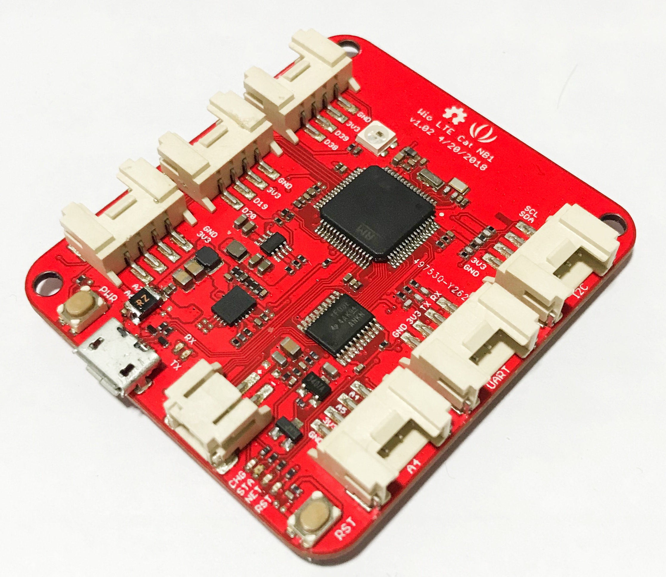
Wio LTE Cat NB1
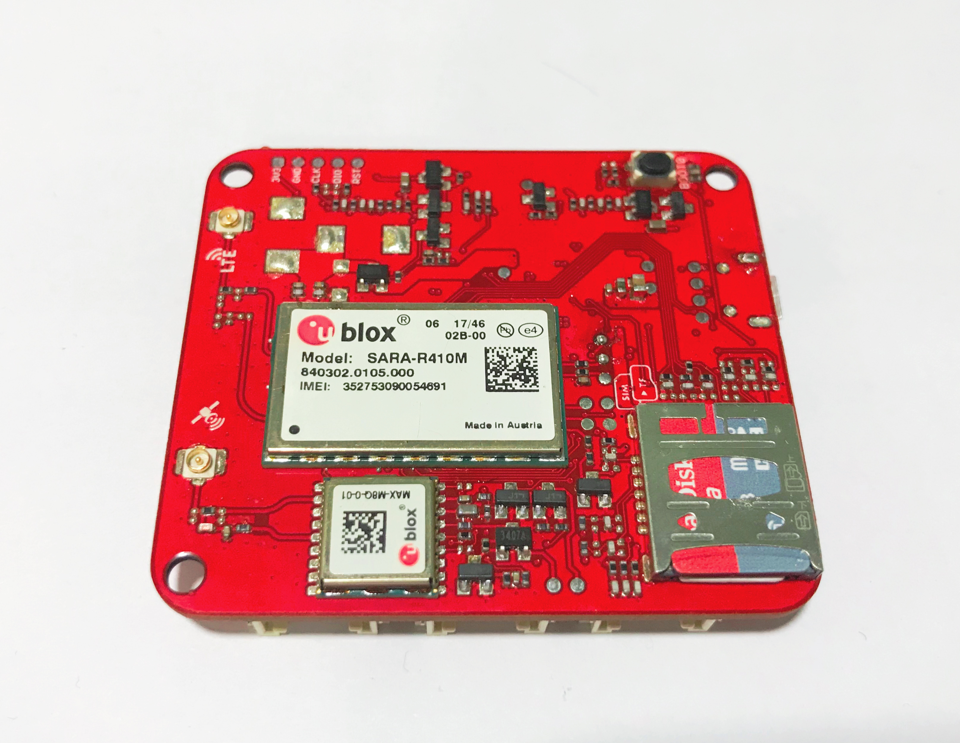
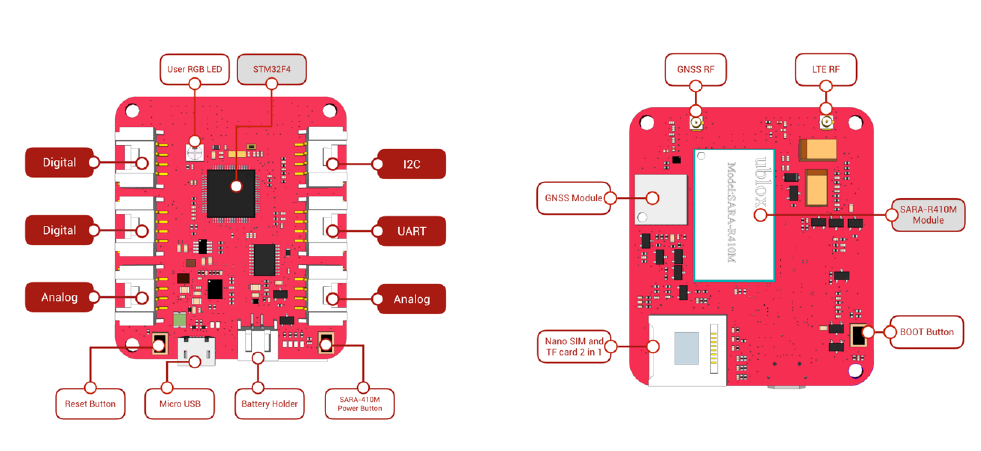
The Wio LTE Cat NB1 is combined with STM32F405RGT6 and external ublox MAX MQ8 GNSS chip and the ublox SARA-R4 LTE Cat NB1 cellular module.
Features
- Embedded power management unit (PMU) featuring ultra-low deep-sleep current consumption
- External GNSS chip can use GPS/BeiDou/GLONASS/Galileo/
- Transplantable and expansible AT Command Library for Wio Tracker
- Arduino IDE compatible
- 6 Grove Connectors
- Nano SIM and TF card 2 in 1 socket
Specification
| Item | Function | Value |
|---|---|---|
| Microcontroller | Processor | STM32F405RG, ARM 32-bit Cortex-M4, 168MHZ |
| Flash Memory | 1MB | |
| SRAM | 192+4KB | |
| Operating Voltage | 3.3V | |
| DC Current per I/O Pin | 7 mA | |
| LTE | LTE Cat.NB1 | AT Command: 3GPP Release 13 and enhanced AT Commands |
| Data | Car NB1 Half-duplex (27.2 kb/s DL, 62.5 UL) | |
| Protocol: IPv4/IPv6/TCP/UDP/FTP/HTTP//HTTPS/FTPS/LTS/MQTT/CoAP | ||
| GNSS | System | GPS/BeiDou/GLONASS/Galileo/ |
| Peripheral | Grove | 2 x Digital Port |
| 2 x Analog Port | ||
| 1 x UART | ||
| 1 x I2C | ||
| Antenna | 1 x LTE Antenna | |
| 1 x GPS Antenna | ||
| Others | USB: Power supply and upload program | |
| JST 1.0 connecter for battery | ||
| MCU Reset Button, MCU Boot (DFU) Button,EC21 Power Button | ||
| 1 x User RGB LED SK6812 | ||
| Nano SIM and TF card 2 in 1 socket | ||
| Size | Length | 54.7mm |
| Width | 48.2mm | |
| Weight | None |
!!!Tip Use Grove modules to expand your application. There are 6 Grove connects on board. If this is your first time to hear about Grove, please put had on Grove System for more details. In brief, Groves is hundreds of sensor that in standard style, which is consist of sensors, actuators, displays as well as communication.
Getting Started
- Wio LTE Cat NB1
- Features
- Specification
- Getting Started
- Install USB driver
- Change DFU driver
- Using Arduino
- Install Seeed STM32F4 Board
- Upload Arduino sketch
- Arduino Example GNSS
- Arduino Example SD Card
- Arduino Example On board RGB LED
- Arduino Example Network RSSI
- Arduino Example TCP
- Arduino Example UDP
- Arduino Example HTTP
- Arduino Example MQTT Subscribe
- Arduino Example MQTT Publish
- Arduino Example CoAP Client
- Arduino Example CoAP Server
- Using Espruino
- FAQ
- Resource
Install USB driver
-
Windows Users: Most versions of Windows won't automatically load the built-in driver for USB com ports. You'll have to download ST's USB driver:
-
Non-Windows XP Users download version 1.4.0 drivers. Unzip the file, run the executable, and then go to C:\Program Files (x86)\STMicroelectronics\Software\Virtual comport driver in Windows Explorer and double-click either dpinst_amd64.exe for 64 bit systems, or dpinst_x86.exe for 32 bit.
-
Windows XP Users download version 1.3.1 drivers. Unzip the file, run VCP_V1.3.1_Setup.exe, and then go to C:\Program Files\STMicroelectronics\Software\Virtual comport driver in Windows Explorer and double-click the executable.
-
-
Linux users to ensure that you have the correct permissions to connect as a normal user you'll need to copy the file 45-espruino.rules to /etc/udev/rules.d, reload rules with udevadm control --reload-rules, and ensure your user is in the plugdev group (you can check by typing groups). You add it by typing sudo adduser $USER plugdev and then logging out and back in. Arch Linux users need to add their user to uucp and lock groups instead.
-
Mac OS X and Chromebook Users: The board will just plug in and work, without drivers!
Change DFU driver
For windows users: Press and hold BOOT button and connect to computer you will see STM32 Device in DFU Mode at device manager, this says that you need to use zadig_xx.exe to change DFU driver from STTub30 to WinUSB as bellow.

Using Arduino
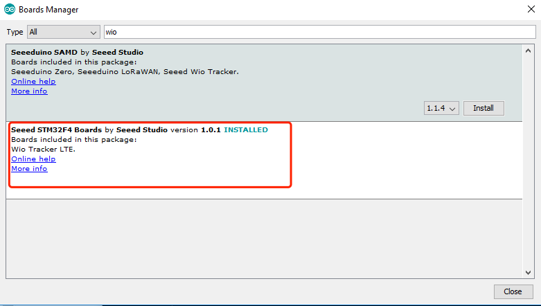
Install Seeed STM32F4 Board
- Step 1. Install Arduino IDE, recommand IDE version upon 1.8.0.
- Step 2. Copy the URL below, open Arduino board manager install Seeed STM32F4 Boards upon version 1.2.1.
https://raw.githubusercontent.com/Seeed-Studio/Seeed_Platform/master/package_legacy_seeeduino_boards_index.json
Upload Arduino sketch
- Step 1. Download WioLTE_Cat_NB1_Arduino_Library from Github. See How to install library to install library for Arduino.
- Step 2. Open example sketch, select File--> Examples-->WioLTE_Cat_NB1_Arduino_Library-->GNSS sketch.
- Step 3. Before uploading the sketch, press and hold both BOOT0 and RST buttons, release the RST button than the BOOT0 button, in this way the board will go into STM BOOLARDER mode.
- Step 4. Don't choose any Serial port to upload the sketch in tools label just click upload icon.
Arduino Example GNSS
- Step 1. Plug the Nano SIM card into Nano SIM slot, near PCB board side.
- Step 2. Select File--> Examples-->WioLTE_Cat_NB1_Arduino_Library-->GNNS-->GNSS sketch.
- Step 3. Press and hold BOOT button at back side of the Wio LTE and plug the USB to PC.
- Step 4. We will see STM BOOLARDER in device manager.
- Step 5. Select Tools-->Boards-->Wio_Tracker_LTE.
- Step 6. Keep COM Port blank.
- Step 7. Select Sketch-->Upload to upload the code to Wio_LTE.
- Step 8. Press RST button to enable the COM port.
#include <ublox_sara_r4_gnss.h>

UBLOX_SARA_R4_GNSS gnss = UBLOX_SARA_R4_GNSS();

void setup()
{
  // Open GNSS module
  gnss.open_GNSS();
  delay(3000);
  Serial.println("_Start");
}

void loop() {
  gnss.dataFlowMode();
}
- Step 9.Use COM monitor tools to print the serial message. Please do not use Arduino IDE COM monitor! That may cause the next time downloading fail, bute reopen Arduino IDE can recover that issue.
- Step 10. We will see lat, lon info printed on screen.
$GNRMC,,V,,,,,,,,,,N*4D
$GNVTG,,,,,,,,,N*2E
$GNGGA,,,,,,0,00,99.99,,,,,,*56
$GNGSA,A,1,,,,,,,,,,,,,99.99,99.99,99.99*2E
$GNGSA,A,1,,,,,,,,,,,,,99.99,99.99,99.99*2E
$GPGSV,1,1,01,30,,,44*7B
$GLGSV,1,1,00*65
$GNGLL,,,,,,V,N*7A
$GNRMC,,V,,,,,,,,,,N*4D
$GNVTG,,,,,,,,,N*2E
$GNGGA,,,,,,0,00,99.99,,,,,,*56
$GNGSA,A,1,,,,,,,,,,,,,99.99,99.99,99.99*2E
$GNGSA,A,1,,,,,,,,,,,,,99.99,99.99,99.99*2E
$GPGSV,1,1,04,07,,,43,17,,,38,18,,,39,30,,,44*70
$GLGSV,1,1,00*65
$GNGLL,,,,,,V,N*7A
$GNRMC,,V,,,,,,,,,,N*4D
$GNVTG,,,,,,,,,N*2E
$GNGGA,,,,,,0,00,99.99,,,,,,*56
$GNGSA,A,1,,,,,,,,,,,,,99.99,99.99,99.99*2E
$GNGSA,A,1,,,,,,,,,,,,,99.99,99.99,99.99*2E
$GPGSV,2,1,06,07,,,44,09,,,41,17,,,40,18,,,41*79
$GPGSV,2,2,06,28,,,40,30,,,45*73
$GLGSV,1,1,00*65
$GNGLL,,,,,,V,N*7A
Arduino Example SD Card
- Step 1. Plug micro SD card to the SD card slot.
- Step 2. Select File--> Examples-->SD-->CardInfo sketch.
- Step 3. Press and hold BOOT button at back side of the Wio LTE and plug the USB to PC.
- Step 4. We will see STM BOOLARDER in device manager.
- Step 5. Select Tools-->Boards-->Wio_Tracker_LTE.
- Step 6. Keep COM Port blank.
- Step 7. Select Sketch-->Upload to upload the code to Wio_LTE.
// include the SD library:
#include <SD.h>

// set up variables using the SD utility library functions:
Sd2Card card;
SdVolume volume;
SdFile root;

// change this to match your SD shield or module;
// Arduino Ethernet shield: pin 4
// Adafruit SD shields and modules: pin 10
// Sparkfun SD shield: pin 8
const int chipSelect = 43;

void setup()
{

  Serial.print("\nInitializing SD card...");
  // On the Ethernet Shield, CS is pin 4. It's set as an output by default.
  // Note that even if it's not used as the CS pin, the hardware SS pin
  // (10 on most Arduino boards, 53 on the Mega) must be left as an output
  // or the SD library functions will not work.
  pinMode(SS, OUTPUT);


  // we'll use the initialization code from the utility libraries
  // since we're just testing if the card is working!
  while (!card.init(SPI_HALF_SPEED, chipSelect)) {
    Serial.println("initialization failed. Things to check:");
    Serial.println("* is a card is inserted?");
    Serial.println("* Is your wiring correct?");
    Serial.println("* did you change the chipSelect pin to match your shield or module?");
  }

  // print the type of card
  Serial.print("\nCard type: ");
  switch(card.type()) {
    case SD_CARD_TYPE_SD1:
      Serial.println("SD1");
      break;
    case SD_CARD_TYPE_SD2:
      Serial.println("SD2");
      break;
    case SD_CARD_TYPE_SDHC:
      Serial.println("SDHC");
      break;
    default:
      Serial.println("Unknown");
  }

  // Now we will try to open the 'volume'/'partition' - it should be FAT16 or FAT32
  if (!volume.init(card)) {
    Serial.println("Could not find FAT16/FAT32 partition.\nMake sure you've formatted the card");
    return;
  }


  // print the type and size of the first FAT-type volume
  uint32_t volumesize;
  Serial.print("\nVolume type is FAT");
  Serial.println(volume.fatType(), DEC);
  Serial.println();

  volumesize = volume.blocksPerCluster();    // clusters are collections of blocks
  volumesize *= volume.clusterCount();       // we'll have a lot of clusters
  volumesize *= 512;                            // SD card blocks are always 512 bytes
  Serial.print("Volume size (bytes): ");
  Serial.println(volumesize);
  Serial.print("Volume size (Kbytes): ");
  volumesize /= 1024;
  Serial.println(volumesize);
  Serial.print("Volume size (Mbytes): ");
  volumesize /= 1024;
  Serial.println(volumesize);


  Serial.println("\nFiles found on the card (name, date and size in bytes): ");
  root.openRoot(volume);

  // list all files in the card with date and size
  root.ls(LS_R | LS_DATE | LS_SIZE);
}


void loop(void) {

}- Step 8. Press RST button to enable the COM port.
- Step 9. Use COM monitor tools to print the serial message. Please do not use Arduino IDE COM monitor! That may cause the next time downloading fail, bute reopen Arduino IDE can recover that issue.
Initializing SD card...
Card type: SDHC

Volume type is FAT32

Volume size (bytes): 2689048576
Volume size (Kbytes): 2626024
Volume size (Mbytes): 2564

Files found on the card (name, date and size in bytes):
Arduino Example On board RGB LED
- Step 1. Select File--> Examples-->WioLTE_Cat_NB1_Arduino_Library-->Seeed_WS2812b sketch.
- Step 2. Press and hold BOOT button at back side of the Wio LTE and plug the USB to PC.
- Step 3. We will see STM BOOLARDER in device manager.
- Step 4. Select Tools-->Boards-->Wio_Tracker_LTE.
- Step 5. Keep COM Port blank.
- Step 6. Select Sketch-->Upload to upload the code to Wio_LTE.
#include <Seeed_ws2812.h>
#include <ublox_sara_r4.h>

#define LEN_NUM 1

Ublox_sara_r4 ublox = Ublox_sara_r4();
WS2812 strip = WS2812(LEN_NUM, ublox.RGB_LED_PIN);

void setup() {
  // Set RGB LED power pin high
  ublox.turnOnRGBPower();
  strip.begin();
  strip.brightness = 20;
}

void loop() {
  strip.RGBCycle(1000);
  strip.rainbowCycle(20);
}- Step 7. Press RST, then you can see the on board RGB LED work.
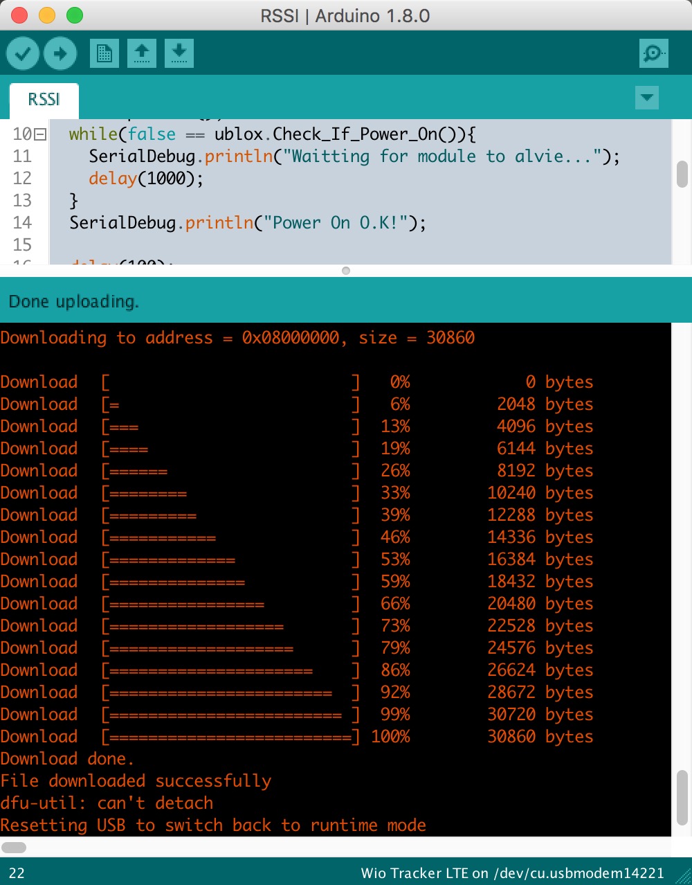
Arduino Example Network RSSI
#include <ublox_sara_r4.h>
#include <UART_Interface.h>

Ublox_sara_r4 ublox = Ublox_sara_r4();

void setup() {

  SerialDebug.println("Begin...");
  ublox.powerOn();
  SerialDebug.print("Waitting for module to alvie...");
  while(false == ublox.isAlive()){
    SerialDebug.print(".");
    delay(100);
  }
  SerialDebug.println("Power On O.K!");

  delay(100);
  check_with_cmd("AT+UGPIOC=23,10\r\n", "OK", CMD);
  check_with_cmd("AT+UGPIOC=16,2\r\n", "OK", CMD);
}

void loop() {
    int signal;
    if(ublox.getSignalStrength(&signal)) {
        SerialDebug.print("RSSI: ");
        SerialDebug.println(signal, DEC);
    } else {
        SerialDebug.print("Error");
    }

    delay(1000);
}
Arduino Example TCP
#include <ublox_sara_r4.h>

Ublox_sara_r4 ublox = Ublox_sara_r4();

char *server = "host";
uint16_t port = 1234;
int sockId = -1;

void setup() {
  Log_info("Begin...");
  ublox.powerOn();
  Log_info("Waitting for module to alvie...");
  while(false == ublox.isAlive()){
    Log(".");
    delay(100);
  }
  Logln();

  Log_info("Initializing network...");
  while(!ublox.network_Init(30000)) {
    Log_error("Network initialize timeout.");
  }
  Log_info("APN: " + String(ublox._apn));
  Log_info("Local IP: " + String(ublox._str_ip));
  Log_info("Operator: " + String(ublox._operator));
  Log_info("Network attached.");

  // This method is import for setting transparent session
  // use disableDirectLinkMode() to use nontransparent session
  ublox.enableDirectLinkMode();

  if(-1 == (sockId = ublox.createSocket(TCP))) {
    Log_error("Create socket error!");
    return;
  }
  if(!ublox.sockConnect(sockId, server, port)) {
    Log_error("connect to server failed.");
  }
  Log_info("Sent TCP message in direct link mode.");

}

void loop() {
  static uint8_t tries = 0;
  String str_msg = "ublox random number " + String(random(0,100));

  ublox.socketWrite((uint8_t *)str_msg.c_str(), (uint16_t)str_msg.length());
  Log_info("Send msg: " + str_msg);

  tries++;
  if(tries > 5) {
    if(ublox.sockClose(sockId)) {
      Log_info("Close socket.");
    }
    Log_info("Enter AT command mode.");
    while(true) AT_bypass();
  }

  delay(2000);
}
Arduino Example UDP
#include <ublox_sara_r4.h>

Ublox_sara_r4 ublox = Ublox_sara_r4();

char *server = "host";
uint16_t port = 1234;
int sockId = -1;

void setup() {
  Log_info("Begin...");

  ublox.powerOn();
  Log_info("Waitting for module to alvie...");
  while(false == ublox.isAlive()) {
    Log(".");
    delay(100);
  }
  Logln("");

  Log_info("Initializing network..");
  while(!ublox.network_Init(30000)) {
    Log_error("Network initialize timeout.");
  }
  Log_info("APN: " + String(ublox._apn));
  Log_info("Local IP: " + String(ublox._str_ip));
  Log_info("Operator: " + String(ublox._operator));
  Log_info("Network attached.");

  if(-1 == (sockId = ublox.createSocket(UDP))) {
    Log_error("Create socket error!");
  }
  Log("[INFO] Create socket id: ");
  Logln(sockId);

  ublox.enableDirectLinkMode();
  if(!ublox.sockConnect(sockId, server, port)) {
    Log_error("connect to server failed.");
  }
  Log_info("Sent UDP message in direct link mode.");
}

void loop() {
  static uint8_t tries = 0;

  String str_msg = "ublox random number " + String(random(0,100));

  ublox.socketWrite((uint8_t *)str_msg.c_str(), (uint16_t)str_msg.length());
  Log_info("Send msg: " + str_msg);

  tries++;
  if(tries > 5) {
    if(ublox.sockClose(sockId)) {
      Log_info("Close socket.");
    }
    while(true) AT_bypass();
  }

  delay(2000);
}
Arduino Example HTTP
To-DO
Arduino Example MQTT Subscribe
#include <Arduino.h>

#include <math.h>

#include <ublox_sara_r4.h>
#include <ublox_sara_r4_mqtt.h>
#include <UART_Interface.h>

#define PRE_FIX  "[MQTT] "

MQTT mqtt;
Ublox_sara_r4 ublox = Ublox_sara_r4();

char *server = "server name or IP";
uint16_t port = 1883;
char *topic = "Heat";

void messageReceived(char* cb_topic, char* cb_msg) {
  Logln(PRE_FIX"incoming msg: ");
  Log("Topic: "); Logln(cb_topic);
  Log("Msg: "); Logln(cb_msg);
}

void setup() {
  Log_info("Begin...");

  ublox.powerOn();
  Log_info("Waitting for module to alive...");
  while(false == ublox.isAlive()) {
    Log(".");
    delay(100);
  }
  Logln();

  Log_info("Initializing network");
  if(!ublox.network_Init(30000)) {
    Log_error("Network initialize timeout.");
    return;
  }

  // Set MQTT server
  if(mqtt.setServer(server, port)) {
    Logln(PRE_FIX"Set mqtt server success.");
  } else {
    Log_error("Set mqtt server failed");
  }

  // Set will
  if(!mqtt.setWill("Heat", "ublox n/r410")) {
    Log_error("Set MQTT will failed");
    return;
  } else {
    Logln(PRE_FIX"Set MQTT will success.");
  }

  // Connect to server
  Logln(PRE_FIX"Connecting to server: " + String(server));
  while(!mqtt.connect()) {}
  Logln(CRLF PRE_FIX"Connected\n\r");

  // Set subscribe
  if(mqtt.subscribe("Heat")) {
    Logln(PRE_FIX"mqtt subscribe topic: " + String(topic));
  } else {
    Log_error("mqtt subscribe failed");
  }

  mqtt.onMessage(messageReceived);

}

void loop() {
    if(mqtt.loop()) {
    return;
  }

  if(mqtt.subscribe("Heat")) {
    Logln(PRE_FIX"mqtt subscribe topic: " + String(topic));
  } else {
    Log_error("mqtt subscribe failed");
  }

}
Arduino Example MQTT Publish
#include <Arduino.h>

#include <math.h>

#include <ublox_sara_r4.h>
#include <ublox_sara_r4_mqtt.h>
#include <UART_Interface.h>

#define PRE_FIX  "[MQTT] "

MQTT mqtt;
Ublox_sara_r4 ublox = Ublox_sara_r4();

char *server = "server name or IP";
uint16_t port = 1883;

void setup() {
  Log_info("Begin...");

  ublox.powerOn();
  Log_info("Waitting for module to alive...");
  while(false == ublox.isAlive()) {
    Log(".");
    delay(100);
  }
  Logln();

  Log_info("Initializing network...");
  if(!ublox.network_Init()) {
    Log_error("Network initialize timeout.");
    return;
  }

  // Set MQTT server
  if(!mqtt.setServer(server, port)) {
    Log_error("Set MQTT server failed");
    return;
  } else {
    Logln(PRE_FIX"Set MQTT server success.");
  }

  // Set will
  if(!mqtt.setWill("Heat", "ublox n/r410")) {
    Log_error("Set MQTT will failed");
    return;
  } else {
    Logln(PRE_FIX"Set MQTT will success.");
  }

  // Connect to server
  Logln(PRE_FIX"Connecting to server: " + String(server));
  while(!mqtt.connect()) {}
  Logln(CRLF PRE_FIX"Connected\n\r");
}

void loop()
{
  static uint8_t tries = 0;
  const char *topic = "Heat";
  String msg = String(random(2000, 3000)*1.0/100.0) + " degree";


  if(mqtt.publish(topic, msg.c_str())) {
    Logln(PRE_FIX" published Topic " + String(topic) + " Messagea " + msg);
  } else {
    Log_error("MQTT publish failed");
    // while(true);
  }

  tries++;
  if(tries > 5)
  {
    if(mqtt.disconnect()) {
      Logln(PRE_FIX"Disconnect.");
    }
    Log_info("Enter AT command loop");
    while(true) AT_bypass();
  }

  delay(2000);
}
Arduino Example CoAP Client
TO-DO
Arduino Example CoAP Server
TO-DO
Using Espruino
Thanks to G.Williams for providing Espruino the Javascript interpreter, so that we can prototype things with Javascript.
Burning Espruino Firmware
- Step 1: Download WioLTE firmware v1.93 or look for espruino_xxx_Wio_LTE.bin here (v1.94 didn't support SD card, please download v1.93).
- Step 2: Install dfu-util, add dfu-util to PATH or Environment Variables, so that we can use it directlly in command line.
- Step 3: Press and hold BOOT0 button before connect to computer, release after connect.
- Step 4: The Wio LTE board will access DFU mode.
- Step 5: In command line windows type dfu-util -d 0483:df11 -c 1 -i 0 -a 0 -s 0x08000000 -D xxx.bin. For windows, Please enter the full path of the bin file.
![]()
Install Espruino web IDE
- Step 1: Install Chrome Web Browser
- Step 2: Click here to get Espruino Web IDE
- Step 3: Run Espruino Web IDE from chrome's home screen or the App Launcher (type chrome://apps* at the address bar)
![]()
How to use Espruino Web IDE
-
Step 1: Connect the Wio LTE board to computer using a micro USB cable. On device manager you can see a new COM Port device, on MacOS it is STM32 Virtual ComPort, on windows it is STMicroelectronic Virtual COM Port.
-
Step 2: On the Web IDE click the left top icon, choose Espruino board in the select box.
![]()
- Step 3: To learn more about the IDE, please click help and then tour as below.
![]()
How to load modules
In Espruino, Modules are pieces of pre-written code (libraries) that perform common tasks, such as interfacing to different bits of hardware.
They can currently be used in a few different ways:
Espruino Web IDE
If you're using the Espruino Web IDE, simply write require("modulename") on the right-hand side - as you would have seen in the reference pages. When you click the Send to Espruino button, the Web IDE will automatically look online for minified versions of the modules you need, download them, and load them onto the board. You don't need an SD card or an internet connection to the Espruino board itself.
Load Module - the default mechanism
If you are using the Web IDE as is, the modules will be loaded from http://www.espruino.com/modules/. This URL can be changed in Web IDE settings.
To save space, most modules are provided as a minified version and the Web IDE tries to load minified versions first with default configuration.
For example, using require("ADNS5050"); will make the Web IDE loading the minified module from http://www.espruino.com/modules/ADNS5050.min.js.
Load Module from Github
For now, as you can type a URL into require, you can actually just pull a module right off GitHub:
require("https://github.com/espruino/EspruinoDocs/blob/master/devices/PCD8544.js");
You can even look at the history of something on GitHub, and can then require a specific version of that file with:
require("https://github.com/espruino/EspruinoDocs/blob/d4996cb3179abe260c030ed02bcb0d2384db6bbd/devices/PCD8544.js");
The URL comes from clicking <> by the commit you were interested in.
Load Module from NPM
If you activate this option in Web IDE, you can load modules from the NPM repository. Right now it:
- only loads the latest version there.
- only works if the module contains a single file.
- can cause some confusion with Espruino's modules, for instance clock.
For example using require("async"); will make the Web IDE loading the tar.gz file (with automatic extraction) of the module from http://registry.npmjs.org/async.
Load Module from local folder
If you are using a local project folder, the Web IDE will automatically create an empty modules folder inside. Put a module there and you can load it with require("myCustomModule");.
![]()
With default Web IDE configuration, it will look for modules following this order:
- local minified
- online minified
- local normal
- online normal
If your own module has the same name as one of the existing ones, the Web IDE will use the minified version from online first.
If you need it anyway, you can provide a local minified version or you can change the Web IDE configuration from .min.js|.js to .js|.min.js or even myCustomModule.js|.min.js|.js to get it working.
Stand-alone Espruino
If you have an Espruino with an SD card (but you're not using the Web IDE), you can copy the modules you need into a directory called 'node_modules' on the SD card. Now, whenever you write require("modulename") the module will be used.
Internet-enabled Espruino
Right now there isn't a way to make Espruino automatically load a module from the internet when required without the Web IDE. This may be added in the future, but the fact that require is synchronous while network connections are asynchronous makes this difficult to do reliably until yield is added into the interpreter.
Until then, the following asyncronous code will dynamically load a module from the internet on demand.
function loadModule(moduleName, callback) {
  require("http").get("http://www.espruino.com/modules/"+moduleName+".js", function(res) {
    var contents = "";
    res.on('data', function(data) { contents += data; });
    res.on('close', function() {
      Modules.addCached(moduleName, contents);
      if (callback) callback();
    });
  }).on('error', function(e) {
    console.log("ERROR", e);
  });
}
Espruino example GPS
TO-DO
Espruino example TCP
To-Do
Espruino example UDP
To-Do
Espruino example Html
To-Do
Espruino example Onboard RGB LED
- Step 1. Config the R, G, B numbers, the arrange is 0~255.
- Step 2. Copy the code to IDE and upload to board.
- Step 3. The on board RBG LED will be turned on.
WioLTE.setLEDPower(true);
WioLTE.LED(r,g,b); // r/g/b is in range of 0..255
// Dynamic colors show
WioLTE.setLEDPower(true);
var rgb = new Uint8ClampedArray(3);
var pos = 0;
function getPattern() {
pos++;
for (var i=0;i<rgb.length;) {
rgb[i++] = (1 + Math.sin((i+pos)*0.1324)) * 10;
rgb[i++] = (1 + Math.sin((i+pos)*0.1654)) * 10;
rgb[i++] = (1 + Math.sin((i+pos)*0.1)) * 10;
}
return rgb;
}
setInterval(function() {
var color = getPattern();
WioLTE.LED(color[0], color[1], color[2]);
}, 100);Espruino example SD Card
Note: espruino firmware v1.94 is not support SD card drive, please use v1.93 or v1.96(May not released)
- Step 1. Plug a micro SD card to the card slot
- Step 2. Copy the code to Espruino IDE and upload it.
var fs = require('fs');

// Init SDCard
WioLTE.init;

// List files
console.log('List files on root path:\r\n', fs.readdirSync());
// Write file
fs.writeFileSync("hello.txt", "Hello World");
// read file
console.log(fs.readFileSync("hello.txt"));
// append file
fs.appendFileSync("hello.txt", "!!!");
// read again
console.log(fs.readFileSync("hello.txt"));
Espruino example Grove Modules
Grove Button
- Step 1. Conenct Grove-Button to Wio LTE D38 port.
- Step 2. Copy the code to IDE and upload to board.
- Step 3. We will see the "Pressed" when we press the button. Or else, we will see "Released" printed on screen.
WioLTE.setGrovePower(true);
var button = new (require("GroveButton"))(WioLTE.D38, function(e) {
  if (e.state) console.log("Pressed");
  else console.log("Released");
});
Grove Ralay
- Step 1. Conenct Grove-Ralay to Wio LTE D38 port.
- Step 2. Copy the code to IDE and upload to board.
- Step 3. We will hear the Relay switch and see the "Done" printed on screen.
WioLTE.setGrovePower(true);
var relay = new (require('GroveRelay'))(WioLTE.D38);
setInterval(function() {
  relay.off();
  relay.pulse(1000, function() {
    console.log("Done!");
});
}, 2000);
Grove Light Sensor
- Step 1. Conenct Grove-Light Sensor to Wio LTE A4 port.
- Step 2. Copy the code to IDE and upload to board.
- Step 3. We will see the numbers printed on screen.
WioLTE.setGrovePower(true);
var light = new (require('GroveLightSensor'))(WioLTE.A4);
setInterval(function() {
  console.log(r.read());
}, 500);
Grove GPS
- Step 1. Conenct Grove-GPS to Wio LTE UART port.
- Step 2. Copy the code to IDE and upload to board.
WioLTE.setGrovePower(true);
Serial1.setup(9600,{tx:WioLTE.UART[1],rx:WioLTE.UART[0]});
var gps = new (require('GPS')).connect(Serial1, function(data) {
  console.log(data);
});- Step 3. We will see time, lat, lon, satellites and altitude info printed on screen as below.
{  "time": "09:35:02", "lat": 30.69766, "lon": 104.05367833333, "fix": 1, "satellites": 6, "altitude": 537.2 }
{  "time": "09:35:03", "lat": 30.69765166666, "lon": 104.05366166666, "fix": 1, "satellites": 6, "altitude": 537.2 }
{  "time": "09:35:04", "lat": 30.69765, "lon": 104.05363833333, "fix": 1, "satellites": 6, "altitude": 537.1 }
Grove 3Axis Digital Accerlerometer(±16g)
- Step 1. Conenct Grove 3-Axis Digital Accerlerometer(±16g) to Wio LTE I2C port.
- Step 2. Copy the code to IDE and upload to board.
WioLTE.setGrovePower(true);
I2C1.setup({scl:WioLTE.I2C[0], sda:WioLTE.I2C[1]});
var accel = require("ADXL345").connect(I2C1,0,0);
accel.measure(true);
setInterval(function(){
  console.log(accel.read());
},2000);- Step 3. We will see x, y and z info printed on screen as below.
{ "x": -0.05859375, "y": -0.46484375, "z": 0.76953125 }
{ "x": -0.0546875, "y": -0.46484375, "z": 0.765625 }
{ "x": -0.0546875, "y": -0.46875, "z": 0.7578125 }
{ "x": -0.05078125, "y": -0.47265625, "z": 0.765625 }
{ "x": -0.0546875, "y": -0.46484375, "z": 0.77734375 }
{ "x": -0.0546875, "y": -0.46875, "z": 0.765625 }
{ "x": -0.0546875, "y": -0.46875, "z": 0.765625 }
{ "x": -0.05078125, "y": -0.47265625, "z": 0.765625 }
Grove Servo
/*
position start form 0.00 to 1.00
*/
function setServo(pin,pos) {

 if (pos<0) pos=0;
 if (pos>1) pos=1;

 analogWrite(pin, (pos * 2.0 + 0.5) / 20, {freq:50});
}

pos = 0.0;
setInterval(function(){
  if(pos >= 1.0) {
    pos = 0.0;
  }
  setServo(WioLTE.D38[0], pos+=0.01);
},20);
Grove Temperature&Humidity Senseor
WioLTE.setGrovePower(true);
var dht = require("DHT11").connect(WioLTE.D38[0]);

/*
A issue may not update with the online DHT11.js, if this demo turns back as
"Temp is -1 and RH is -1", please uncomment the block below for rewrite the read method"
*/

/*
dht.read = function (cb, n) {
  if (!n) n=10;
  var d = "";
  var ht = this;
  pinMode(ht.pin); // set pin state to automatic
  digitalWrite(ht.pin, 0);
  setTimeout(function() {
    this.watch = setWatch(function(t) {
      d+=0|(t.time-t.lastTime>0.00005);
    }, ht.pin, {edge:'falling',repeat:true} );
  },18);
  // setTimeout(function() {pinMode(ht.pin,'input_pullup');},1);
  setTimeout(function() {
    clearWatch(ht.watch);
    delete ht.watch;
    var cks =
        parseInt(d.substr(2,8),2)+
        parseInt(d.substr(10,8),2)+
        parseInt(d.substr(18,8),2)+
        parseInt(d.substr(26,8),2);
    if (cks&&((cks&0xFF)==parseInt(d.substr(34,8),2))) {
      cb({
        raw : d,
        rh : parseInt(d.substr(2,8),2),
        temp : parseInt(d.substr(18,8),2)
      });
    } else {
      if (n>1) setTimeout(function() {ht.read(cb,--n);},500);
      else cb({err:true, checksumError:cks>0, raw:d, temp:-1, rh:-1});
    }
  }, 50);
};
*/

setInterval(function(){
  dht.read(function (a) {
  console.log("Temp is "+a.temp.toString()+" and RH is "+a.rh.toString());
});
}, 3000);
Javascript APIs
For more info, please refer to Wio_LTE_Module
- debug(boolean, boolean) - choose debug level
- reset(callback) - Reset LTE
- init(callback) - Initialise LTE
- getVersion(callback) - returns LTE firmware version
- connect(apn, username, password, callback) - Connect to mobile network
- getVersion(callback) - returns current version
- getIP(callback) - Get current IP address
- geoLocStart(period_in_milliseconds) - Start getting geolocation data
- geoLocStop() - Stop getting geolocation data
- geoLocGet(callback) - Get last location
- geoLocConvert(callback(err,latlong)) - Get last location as latitude/longitude
- board.SMS - SMS functionality with init/read/send/list/delete functions based on the [[ATSMS]] module
- sleep(callback) - LTE modem get into sleep mode, it can save about 100mA
- wake(callback) - LTE modem wake up from sleep mode
FAQ
Please click here to see all Wio_LTE FAQs.
Resource
- [Eagle]Wio LTE Cat NB1 v1.02
- [Library]Wio_LTE_Arduino_Library
- [Datasheet]AT Command