jmacarthur / Zeta256
Labels
Projects that are alternatives of or similar to Zeta256
zeta256
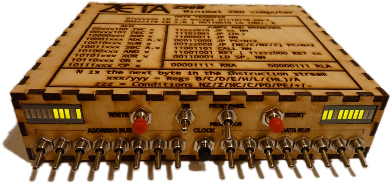
The Zeta is a minimal Z80 toggle-switch computer. It has a Zilog Z80 microprocessor, 256 bytes of RAM and the only interface is the front panel which directly sets and reads the address and data buses.
There is a video of it executing Euclid's algorithm:
https://www.youtube.com/watch?v=0GmY_UrbXnA
At the moment, there is only one real source file in this repository, an Inkscape-produced SVG which contains the stripboard layout and lasercut paths along with the image for the box top. In the future I'll try to add a KiCad circuit diagram. This file doesn't preview well in github because there are some very thin and zero-width lines - turn on outline mode (View -> Display mode -> Outline) in Inkscape to view it.
Note that this isn't a foolproof guide to building a replica - there are several parts not recorded yet, such as where to cut the track on the stripboard, and some extra components for the voltage regulators.
There are some errata in the current source - please see the issues section for details.
Why is your circuit diagram in SVG?
Because of the number of DIP chips in this project, it suits stripboard well, and I haven't found a good program for designing stripboard layouts yet. Fritzing supports small stripboard, but has performance problems when you use a layout as big as this one.
Update, 28th Februray 2016: Samuel Doye has sent in a KiCad project with a schematic layout!
How does it work?
The Z80 has two pins called !BUSREQ and !BUSACK. !BUSREQ is an input, normally high (5V), which means the Z80 is in control of the address and data buses, except when RD is high which means the RAM chip can control the data bus. The "Front Panel/Processor" switch on the front panel pulls !BUSREQ to 0V when "Front Panel" is selected. After a few clock cycles, the Z80 will then drop the output !BUSACK. This is connected to the output enable pins of the two input buffers (the SN74LVC245AN chips). The switch positions are then driven onto the buses, and you can enter data into the RAM using the write button.
The inverting schmitt trigger IC (74HCT14) performs debouncing for the clock line, and inverts and debounces the reset button. None of the other inputs are debounced. There are three spare inverters on the 74HCT14 chip, which is enough to make a basic clock generator if you wanted this to run at more than a few hertz.
The rotary switch is a 10 or 16 position encoded switch with the '1' line connected to the clock line and the common connector to 5V. Note that if you leave the rotary switch in an 'odd' position, the front panel clock button will not do anything.
The RAM is a 32 kilobyte static RAM chip, but only address lines 0-7 are connected, so all memory will alias the 0-255 byte range. You could fairly easily wire up some more address lines. With a bit of creative programming, you could even use that memory without adding more address switches. I don't think anyone will be sufficiently interested to toggle in a program larger than 256 bytes, though.
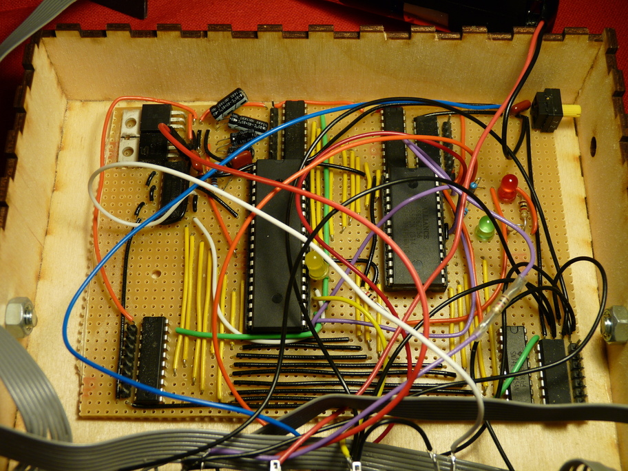
Photo of circuit board
There are three extra LEDs added to this which aren't on the circuit diagram. They are connected via a 1k resistor to 5V and the !WR, !RD and !M1 lines which show when memory is being written to and read, and when the CPU is performing an instruction fetch. These help when debugging.
Whatever you do, don't assemble this on tripad board. I did because Maplin never stock proper stripboard. The underside of this board looks appalling.
If you want to build this...
Please bear in mind that there may be errors in any of the diagrams or instructions here. Like all my projects, I usually only build things once and write up the documentation afterwards, so it's quite possible I've omitted stages. Please make sure you understand what you're building before buying any components. I can sometimes offer some help by email, but ultimately I do not make any guarantees that this project will work.
Thanks
The KiCad files were made by Samuel Doye.
The design owes a few elements to MarcusB's minimal Z80 computer, which can be found here:
http://letsmakerobots.com/blog/markusb/i-am-building-z80-computer
The case started out as a box from Rahul's BoxMaker:


