biologist79 / Espuino
Projects that are alternatives of or similar to Espuino
ESPuino - rfid-based musiccontroller based on ESP32 with I2S-DAC-support
NEWS
- EN: I've set up a primarily German-speaking community with much documentation. Also an international corner for non-German-speakers is available at https://forum.espuino.de. Github-Login can be used there but it's not necessary.
- DE: Ich habe ein primär deutschsprachiges Forum aufgesetzt, welches ich mit reichlich Doku versehen habe. Würde mich freuen, euch dort zu sehen: https://forum.espuino.de. Ihr könnt euch dort mit eurem Github-Login einloggen, jedoch auch "normal" anmelden. Dokumenation findet ihr insbesondere hier: https://forum.espuino.de/c/dokumentation/anleitungen/10
Changelog
Moved to another location as it became to prominent here. Only last three events are kept:
- 26.02.2021: Shutdown via webgui is now available.
- 05.03.2021: Added support for remote control via infrared. Make sure to enable
IR_CONTROL_ENABLEto use this feature and don't forget to assign corresponding rc-commands of your remote control to actions. - 19.03.2021: Added support for port-expander PCA9555. Can be used for everything, that is "button-like": buttons, headphone-detect, PN5180.IRQ.
Known bugs
- Some webstreams don't run. Guess it's a combination of saturated connection-pool and lack of heap-memory. Works probably better if ESP32-WROVER (e.g. Lolin D32 pro) is used, as this chip has PSRAM. Advice: Don't enable modules (e.g. MQTT) if you don't need them as this could save memory (and trouble).
- English translation/version for webgui is currently pretty outdated. This will be fixed soon when i18n-support will be integrated.
ESPuino - what's that?
The basic idea of ESPuino is to provide a way, to use the Arduino-platform for a music-control-concept that supports locally stored music-files without DRM-restrictions. This basically means that RFID-tags are used to direct a music-player. Even for kids this concept is simple: place an RFID-object (card, character) on top of a box and the music starts to play. Place another RFID-object on it and anything else is played. Simple as that.
The core of my implementation is based on the popular ESP32 by Espressif. Having WiFi-support out-of-the-box makes it possible to provide further features like an integrated FTP-server (to feed the player with music), smarthome-integration via MQTT, webradio and administration via webgui. And nonetheless Bluetooth, too! However, my primary focus was to port the project to a modular base. Having said this mp3-decoding is done in software with a dedicated µSD-card-slot and music-output is done via I2S-protocol. I did all my tests on Adafruit's MAX98357A, UDA1334 and headphone-pcb. Hopefully, not only in theory, other DACs that support I2S can be used as well.
Hardware-setup
The heart of my project is an ESP32 on a Wemos Lolin32 development-board. If ordered in China (Aliexpress, eBay e.g.) it's pretty cheap (around 4€) but even in Europe it's only around 8€. Make sure to install the drivers for the USB/Serial-chip (CP2102 e.g.). But probably it's better to use it's successor (which has battery-measurement already included): Wemos Lolin D32. Or, if you're planning to enjoy webstreams regularly, Wemos Lolin D32 pro might be a good decision. It comes with µSD-slot onboard and because of its ESP32-WROVER-B, it has PSRAM included. PSRAM is used as webstream-cache and might be used more intensively in future by ESPuino in general.
- MAX98357A (like Adafruit's)
- µSD-card-reader; 3.3V only; supports SPI + SD-MMC or cheaper
- RFID-reader RC-522
- RFID-reader PN5180
- RFID-tags
- Neopixel-ring
- Rotary Encoder
- Buttons
- Speaker
- µSD-card: doesn't have to be a super-fast one; µC is limiting the throughput. Tested 32GB without any problems.
- µSD in SD-MMC (1 Bit) mode: Several devkits with onboard SD slot have support for this mode, e.g.: (https://de.aliexpress.com/item/4001229463219.html)
- optional replace the RFID-reader with a the better one: PN5180 comes with better RFID-range, less power-consumption and support for ISO-15693 / iCode SLIX2 tags (https://www.bing.com/shop?q=pn5180&FORM=SHOPTB)
Getting Started
- Arduino-IDE can be used but you need to satisfy dependencies for all the libraries listed in
platformio.inimanually. - Instead I recommend to install Microsoft's Visual Studio Code. This is a popular and powerful IDE that gives you the ability to install tons of (well-supported) plugins.
- Install Platformio Plugin into Visual Studio Code and make sure to have a look at the documentation. Step-by-step-manual is available here
- Install Git and make a copy ("clone") my repository to your local computer using
git clone https://github.com/biologist79/ESPuino.git. Using git you can keep your local repository easily up to date without doing copy'n'paste. To keep it up to date rungit pull origin master. Further infos [here}(https://stackoverflow.com/questions/1443210/updating-a-local-repository-with-changes-from-a-github-repository). - (Optional) Install Gitlens as plugin (to have advanced Git-support).
- Now, that the git-repository is saved locally, import this folder into Platformio as a project.
- There's a file called
platformio.ini, that contains the configuration for different develboards (e.g. env:lolin32). Platformio supports hundrets of boards out of the box. So probably you need to change/extend that configuration. Guess Lolin32 is described in platformio.ini but you need Lolin D32, then lookup Platformio's documentation to know what to change. - Depending on your operating system (Windows, Mac OS, Linux), you probably need to change
upload_portandmonitor_portas well. - Edit
src/settings.haccording your needs. Especially don't forget to setHALdepending on your develboard. - Edit board-specific (
HAL) config-file (e.g.settings-lolin32.hfor Lolin32 orsettings-lolin_d32.hfor Lolin D32). If you're running a board that is not listed there: start withsettings-custom.hand change it according your needs. - Connect your develboard via USB, click the alien-head to the left and run
Upload and Monitor. All libraries necessary should be fetched in background now followed by code-compilation. After that, your ESP32 is flashed with the firmware. Depending on your develboard it might me necessary to push a button in order to allow ESP32 to enter flashmode (not necessary für Lolin32, D32 und D32 pro). - Now have a look at the serial-output at the bottom of Visual Studio Code's windows. At the first run there might appear a few error-messages (related to missing entries in NVS). Don't worry, this is just normal. However, make sure SD is running as this is mandatory!
- If everything ran fine, at the first run, ESPuino should open an access-point with the name "ESPuino". Join this WiFi with your computer (or mobile) and enter
192.168.4.1to your webbrowser. Enter WiFi-credentials and the hostname. After saving the configuraton, restart ESPuino. Hint: I tried to connect this access-point via Android mobile. Basically that's no problem, but as my mobile detected there'd be no internet-connection, it keept LTE-connection open and prevented me from connecting to192.168.4.1. So if in doubts use a computer. - After reboot ESPuino tries to join your WiFi (with the credentials previously entered). If that was successful, an IP is shown in the serial-console of Visual Studio Code. You can call ESPuino's GUI using a webbrowser via this IP; make sure to allow Javascript. If mDNS-feature is active in
src/settings.h, you can use the hostname configured extended by .local instead the IP. So if you configuredespuinoas hostname, you can useespuino.localfor webgui and FTP. - Via FTP you can upload data (but don't expect it to be super fast). It's round about 185 kb/s if SD is in SPI-mode and 310 kB/s if SD is in MMC-mode.
- FTP needs to be activated after boot! Don't forget to assign action
ENABLE_FTP_SERVERinsettings.hto be able to activate it. Neopixel flashes green (1x) if enabling was successful. It'll be disabled automatically after next reboot. Means: you have to enable it every time you need it (if reboot was in between). Sounds annoying and maybe it is, but's running this way in order to have more heap-memory available (for webstream) if FTP isn't running. - Via webbrowser you can configure various settings and pair RFID-tags with actions. If MQTT/FTP-support was not compiled, their config-tabs won't appear.
Prerequisites / tipps
- Open settings.h
- choose if optional modules (e.g. MQTT, FTP, Neopixel) should be compiled/enabled
- Make sure to edit/review button-layout. Default-design is three buttons and a rotary-encoder. All actions available are listed in
values.h(values >= 100). - For debugging-purposes serialDebug can be set to ERROR, NOTICE, INFO or DEBUG.
- If MQTT=yes, set the IP or hostname of the MQTT-server accordingly and check the MQTT-topics (states and commands)
- Advice: don't enable MQTT if there's no broker around because network-timeouts can really be a PITA.
- If Neopixel enabled: set NUM_LEDS to the LED-number of your Neopixel-ring and define the Neopixel-type using
#define CHIPSET - If you're using Arduino-IDE please make sure to change ESP32's partition-layout to
Huge Appas otherwise the sketch won't fit into the flash-memory. - Open board-specific config-file and edit according your needs.
- If you want to monitor battery's voltage, make sure to enable
MEASURE_BATTERY_VOLTAGE. Use a voltage-divider as voltage of a LiPo is way too high for ESP32 (only 3.3V supported!). For my tests I connected VBat with a serial connection of 130k + 130k resistors (VBat(+)--130k--X--130k--VBat(-)). X is the measure-point where to connect the GPIO to. If using Lolin D32 or Lolin D32 pro, make sure to leave both resistor-values unchanged at 100k. Same for GPIO: unchanged at 35. Please note: via GUI upper and lower voltage cut-offs for visualisation of battery-voltage (Neopixel) is available. Additional GUI-configurable values are interval (in minutes) for checking battery voltage and the cut off-voltage below whose a warning is shown via Neopixel. - If you're using a headphone-pcb with a headphone jack that has a pin to indicate if there's a plug, you can use this signal along with the feature
HEADPHONE_ADJUST_ENABLEto limit the maximum headphone-voltage automatically. As per default you have to invert this signal (with a P-channel MOSFET) and connect it to GPIO22. - Enabling
SHUTDOWN_IF_SD_BOOT_FAILSis really recommended if you run your ESPuino in battery-mode without having a restart-button exposed to the outside of ESPuino's enclosure. Because otherwise there's no way to restart your ESPuino and the error-state will remain until battery is empty (or you open the enclosure, hehe). - Enabling
PLAY_LAST_RFID_AFTER_REBOOTwill tell ESPuino to remember the last RFID-tag played after next reboot. So rebooting ESPuino will end up in autoplay. I don't really recommend this feature because if you use it along with a webstream, in case of streaming-issues this might end up in an infinite loop.
SD-card: SPI or SD-MMC (1 bit)-mode?
Having SD working is mandatory. However, there are two modes available to access SD-cards: SPI and SD-MMC (1 bit).
Advantages SD-MMC (1 bit) over SPI:
- Needs only three GPIOs (instead of four)
- It's faster. FTP-upload: 298 kiB vs 178 kiB. HTTP-upload: 372 kiB vs 184 kiB. (tested with filesize of 70.7 MiB.
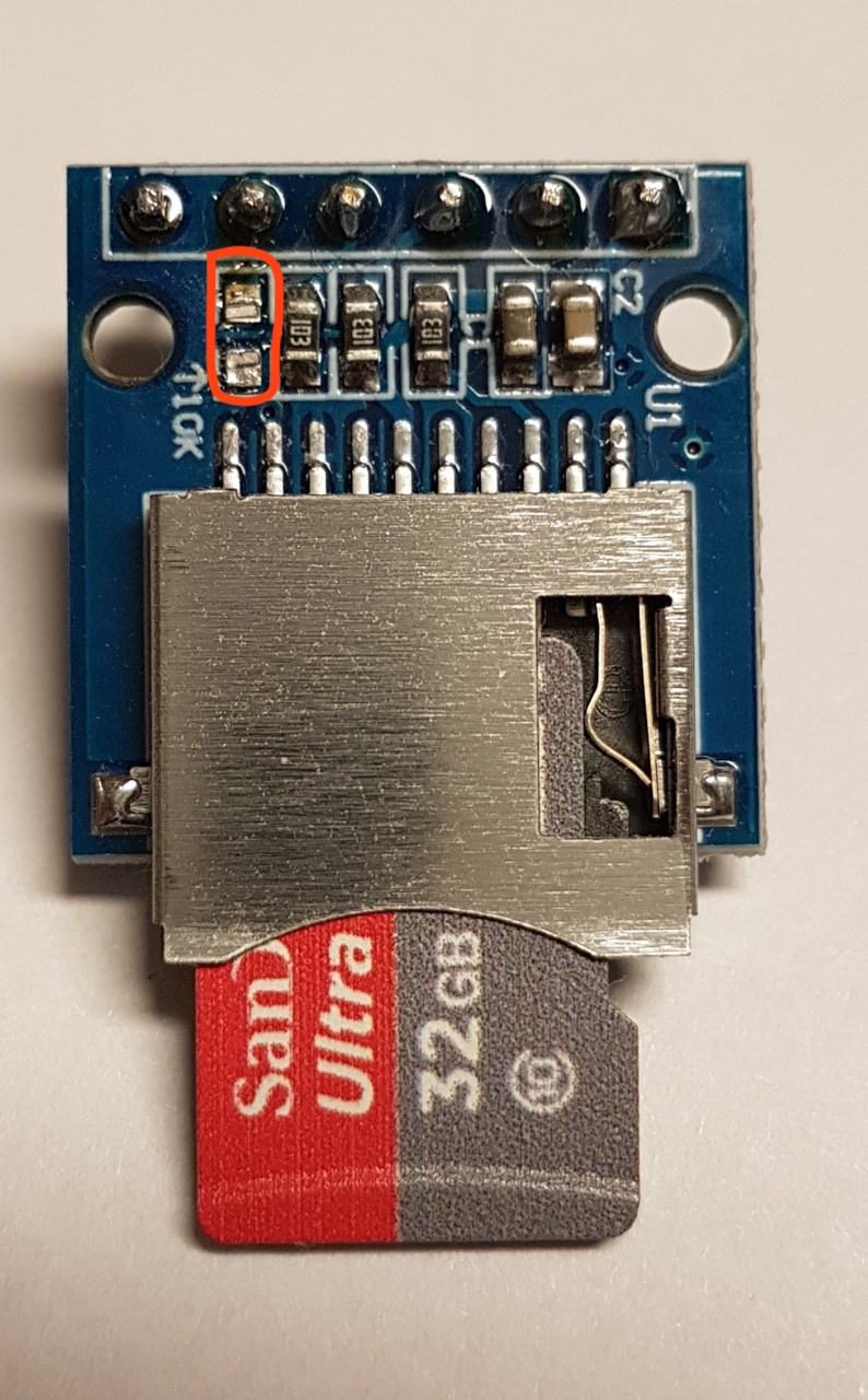
So why using SPI if SD-MMC seems to be better? The primary problem of SD-MMC is: you cannot choose different GPIOs. That doesn't sound bad but this can (depending on the µSD-card-reader-module) be a problem because maybe GPIO2 is pulled HIGH to 3.3V by a 10k-resistor. For example this is the case when using the reader-module named above in hardware-setup. It's a problem because if GPIO2 is pulled high at boot, ESP32 doesn't enter flash-mode. As soon as flash-mode is entered, it's no longer a problem. However, this behaviour can be an issue if ESP32 is deeply "burried" in ESPuino's enclosure and you want to update its firmware. But fortunately there's a way to bypass this problem: remove the pullup-resistor shown in the picture. It can be removed safely because if MMC-mode is set, pullup is done in software usingpinMode(2, INPUT_PULLUP);. So it's not really a problem but you have to take note of that!
RFID: RC522 or PN5180?
RC522 is so to say the Tonuino-standard. It's cheap and works, but RFID-tag has to be placed near the reader. PN5180 instead has better RFID range/sensitivity and can read ISO-15693 / iCode SLIX2-tags aka 'Tonies' (you need a password to read Tonies). You can also wake-up the board with the card. Disadvantages: is a bit more expensive and needs more GPIOs (6/7 instead of 4). Refer PN5180's wire-section below for further informations. Hint: if using 3.3V make sure to connect PN5180 to +5V AND 3.3V. Sounds weird but it's necessary.
3.3 or 5V?
- Why 3.3V? Because: if you plan to use battery-mode with a LiPo, there's no 5 V available (unless USB is connected). That's why my design's focus is 3.3 V. If you want to use 5 V - do so, but be advised it's not compatible with LiPo-battery-mode. The Mosfet-circuit for saving power in deepsleep (see Lolin32-schematics as reference) works as well for 5 V.
- MAX98357a: provides more power at 5 V but also runs at 3.3 V. Anyway: it's still loud enough (in my opinion).
- Neopixel: specification says it needs 5 V but also runs at 3.3 V.
- RC522: needs 3.3 V (don't power with 5 V!)
- PN5180: at 3.3 V make sure to connect both 5 V and 3.3 V-pins to 3.3 V.
- SD: needs 3.3 V but if voltage-regulator is onboard, it can be connected to 5 V as well
- Rotary encoder: 3.3 V (don't power with 5 V! Encoder doens't care if connected to 3.3 or 5 V, but GPIOs of ESP32 do!)
Wiring (general)
Depending on the develboard you're using and the needs you have, there are different options available.
A lot of wiring is necessary to get ESPuino working. After my first experiments on a breadboard I soldered all the stuff onto a PCB in order to avoid wild-west-cabling. Especially for the interconnect between µC and µSD-card-reader make sure to use short wires (like 10cm or so)! As of my experience with a breadbord, male/male-connectors are better than female/female-connectors. Important: you can easily connect another I2S-DACs by just connecting them in parallel to the I2S-pins (DIN, BCLK, LRC). This is true for example if you plan to integrate a line/headphone-pcb. In general, this runs fine. But unfortunately especially this board lacks of a headphone jack, that takes note if a plug is inserted or not. Best way is to use a headphone jack that has a pin that is pulled to GND, if there's no plug and vice versa. Using for example a MOSFET-circuit, this GND-signal can be inverted in a way, that MAX98357.SD is pulled down to GND if there's a plug. Doing that will mute MAX98537a and so turn off the speaker immediately if there's a plug and vice versa. Have a look at the PCB-folder in order to view the detailed solution. Here's an example for such a headphone-pcb that makes use of GND.
Have a look at the PCB-folder. I provided PCBs for a number of develboards. Probably this makes things easier for you.
Wiring (2 SPI-instances: RC522 + SD + 3 buttons + rotary-encoder)
Uses two SPI-instances. The first one for the RFID-reader and the second for SD-card-reader. This is also the setup, I personally use.
| ESP32 (GPIO) | Hardware | Pin | Comment |
| ------------- | --------------------- | ------ | ------------------------------------------------------------ |
| 3.3 (5) V | SD-reader | VCC | Connect to p-channel MOSFET for power-saving when µC is off |
| GND | SD-reader | GND | |
| 15 | SD-reader | CS | |
| 13 | SD-reader | MOSI | |
| 16 | SD-reader | MISO | |
| 14 | SD-reader | SCK | |
| 3.3 V | RFID-reader | 3.3V | (Connect directly to GPIO 17 for power-saving when µC is off) |
| GND | RFID-reader | GND | |
| 21 | RFID-reader | CS/SDA | |
| 23 | RFID-reader | MOSI | |
| 19 | RFID-reader | MISO | |
| 18 | RFID-reader | SCK | |
| 5 / 3.3 V | MAX98357 | VIN | Connect to p-channel MOSFET for power-saving when µC is off |
| GND | MAX98357 | GND | |
| 25 | MAX98357 | DIN | |
| 27 | MAX98357 | BCLK | |
| 26 | MAX98357 | LRC | |
| --- | MAX98357 | SD | Info: if pulled down to GND amp will turn off |
| 34 | Rotary encoder | CLK | Change CLK with DT if you want to change the direction of RE |
| 35 | Rotary encoder | DT | Change CLK with DT if you want to change the direction of RE |
| 32 | Rotary encoder | BUTTON | |
| 3.3 V | Rotary encoder | + | |
| GND | Rotary encoder | GND | |
| 4 | Button (next) | | |
| GND | Button (next) | | |
| 2 | Button (previous) | | |
| GND | Button (previous) | | |
| 5 | Button (pause/play) | | |
| GND | Button (pause/play) | | |
| 3.3 V | Neopixel | V | Connect to p-channel MOSFET for power-saving when µC is off |
| GND | Neopixel | G | |
| 12 | Neopixel | DI | |
| 17 | N-channel Mosfet | Gate | |
| 33 | Voltage-divider / BAT | | Optional: voltage-divider to monitor battery-voltage |
| 22 | Headphone jack | | Optional: if pulled to ground, headphone-volume is set |
Optionally, GPIO 17 can be used to drive a Mosfet-circuit in order to switch off peripherals (SD, Neopixel, RFID and MAX98357a) if ESP32 is in deepsleep. Please refer the schematics for my Lolin32-PCB for further informations. If you need further informations on transistor-circuits visit this website.
In general I recommend using a µSD-card-reader that can be run solely with 3.3V (doesn't have a voltage-regulator). This is because if 3.3V go through the voltage regulator a small voltage-drop will be introduced, which may lead to SD-malfunction as the resulting voltage is a bit too low. Vice versa if you want to connect your reader solely to 5V, make sure to have one WITH a voltage regulator :-). And by the way: when LiPo-battery is connected, there's no 5V. That's why I designed my Lolin-PCBs with 3.3V only.
Wiring (SD-card in 1 Bit SD-MMC mode) different to above
| ESP32 (GPIO) | Hardware | Pin | Comment |
|---|---|---|---|
| -- | SD-reader | CS | no CS required |
| 15 | SD-reader | MOSI | |
| 2 | SD-reader | MISO | make sure there's no hardware-pullup for MISO |
| 14 | SD-reader | SCK |
Make sure to enable SD_MMC_1BIT_MODE if you want to use this feature. Don't(!) enable SINGLE_SPI_ENABLE. SD-MMC-mode requires these fixed PINs listed above. You can find a good comparison of different SD-card-modes here: (https://www.instructables.com/Select-SD-Interface-for-ESP32/).
Advice: Double check that above PINs are not used elsewhere (e.g. GPIO2 is used as PREVIOUS_BUTTON as per default in settings.h).
Wiring (1 SPI-instance: RC522 + SD + 3 buttons + rotary-encoder) [EXPERIMENTAL, maybe not working!]
Basically the same as using 2 SPI-instances but... In this case RFID-reader + SD-reader share SPI's SCK, MISO and MOSI. But make sure to use different CS-pins. Have to admit I had some problems to get this running. Seems to be connected properly, but nothing happens when an RFID-tag is applied. Maybe anybody else wants to point out :-)
| ESP32 (GPIO) | Hardware | Pin | Comment |
|---|---|---|---|
| 3.3 (5) V | SD-reader | VCC | Connect to p-channel MOSFET for power-saving when µC is off |
| GND | SD-reader | GND | |
| 15 | SD-reader | CS | Don't share with RFID! |
| 3.3 V | RFID-reader | 3.3V | Connect directly to GPIO 17 for power-saving when µC is off |
| GND | RFID-reader | GND | |
| 21 | RFID-reader | CS/SDA | Don't share with SD! |
| 23 | RFID+SD-reader | MOSI | |
| 19 | RFID+SD-reader | MISO | |
| 18 | RFID+SD-reader | SCK | |
| 5 / 3.3 V | MAX98357 | VIN | Connect to p-channel MOSFET for power-saving when µC is off |
| GND | MAX98357 | GND | |
| 25 | MAX98357 | DIN | |
| 27 | MAX98357 | BCLK | |
| 26 | MAX98357 | LRC | |
| --- | MAX98357 | SD | Info: if pulled down to GND amp will turn off |
| 34 | Rotary encoder | CLK | Change CLK with DT if you want to change the direction of RE |
| 35 | Rotary encoder | DT | Change CLK with DT if you want to change the direction of RE |
| 32 | Rotary encoder | BUTTON | |
| 3.3 V | Rotary encoder | + | |
| GND | Rotary encoder | GND | |
| 4 | Button (next) | ||
| GND | Button (next) | ||
| 2 | Button (previous) | ||
| GND | Button (previous) | ||
| 5 | Button (pause/play) | ||
| GND | Button (pause/play) | ||
| 5 / 3.3 V | Neopixel | V | Connect to p-channel MOSFET for power-saving when µC is off |
| GND | Neopixel | G | |
| 12 | Neopixel | DI | |
| 17 | N-channel Mosfet | Gate | |
| 33 | Voltage-divider / BAT | Optional: voltage-divider to monitor battery-voltage | |
| 22 | Headphone jack | Optional: if pulled to ground, headphone-volume is set |
Wiring (PN5180 instead of MFRC522) different to above
PN5180-reader needs at least two more GPIOs: RESET and BUSY. Double check pin-conflicts! RFID_READER_TYPE_PN5180 needs to be enabled to use this feature. Make sure to disable RFID_READER_TYPE_MFRC522 if doing so!
You can enable low power card-detection with PN5180_ENABLE_LPCD, but this needs another GPIO for IRQ. With low power card detection (LPCD) you can wake-up the ESP32 from deep-sleep just by applying a card to the reader. You need a PN5180-firmware >= 4.0. Most china-boards comes with older firmware. The latest firmware can be flashed with this project.
| ESP32 (GPIO) | Hardware | Pin | Comment |
|---|---|---|---|
| 3.3 V | PN5180 RFID-reader | 3.3V | Connect directly to GPIO 17 for power-saving when µC is off |
| 3.3 V | 3.3V | For low power card detection mode (LPCD) connect directly to 3.3V | |
| 5 / 3.3 V | PN5180 RFID-reader | 5V | Don't forget to connect this pin the same way as 3.3V |
| GND | PN5180 RFID-reader | GND | |
| 21 | PN5180 RFID-reader | CS/SDA | Same as MFRC522. Don't share with SD! |
| 23 | PN5180 RFID-reader | MOSI | Same as MFRC522 |
| 19 | PN5180 RFID-reader | MISO | Same as MFRC522 |
| 18 | PN5180 RFID-reader | SCK | Same as MFRC522 |
| 16 | PN5180 RFID-reader | BUSY | be aware of SD MISO if running in SPI mode |
| 22 | PN5180 RFID-reader | RST | be aware of Headphone jack PIN |
| 39 | PN5180 RFID-reader | IRQ | optional, used for low power card detection (LPCD) |
Wiring (custom) / different pinout
When using a develboard with SD-card-reader already integrated (Lolin D32 Pro, several TTGO-boards), the pinouts described above my not fit. Feel free to change them according your needs. Additionaly some boards may use one or some of the GPIOs I used for their internal purposes and that reason for are maybe not exposed via pin-headers. However, having them exposed doesn't mean they can be used without limits. This is because some GPIOs have to be logical LOW or HIGH at start/boot for example and this is probably not the case when connecting stuff to it. Feel free to adjust the GPIOs proposed by me (but be adviced it could take a while to get it running). If you encounter problems please refer the board's manual first.
Here I described a solution for a board with many GPIOs used internally and a very limited number of GPIOs exposed. That's why I had to use different SPI-GPIOs for RFID as well. Please note I used a slightly modified RFID-lib there. Please note: the code-basis is outdated. Will need to re-integrate it into my master-branch...
WiFi
WiFi is mandatory for webgui, FTP and MQTT. However, WiFi can be temporarily or permanently disabled. There are two ways to do that:
- Use a special modification-card that can be configured via webgui
- Press previous-key (and keep it pressed) + press next-button in parallel shortly. Now release both. This toggles the current WiFi-status: if it's currently enabled, it will be disabled instantly and vice versa. Please note: this WiFi-status will remain until you change it again, which means, that ESPuino will remember this state after the next reboot. Having Wifi enabled is indicated in idle-mode (no playlist active) with four white slow rotating LEDs whereas disabled WiFi is represented by those ones coloured green. Bluetooth-mode is indicated by blue LEDs.
Bluetooth
ESPuino can be used as bluetooth-sink (a2dp). This mode can be enabled/disabled via a RFID-modification-card. Applying one will restart ESPuino immediately. Two modes are available which are toggled in between: "normal" and "bluetooth". Normal means: SD + WiFi are available whereas in mode "bluetooth" only bluetooth-support can be provided. If bluetooth is active, this is indicated by four slow rotating blue LEDs. Now you can stream to your ESPuino e.g. with your mobile device. Tested this with Android 8 and worked 100% flawless.
Port-expander
There might be situations where you run out of GPIOs. To address this, port-expander PCA9555 can be used to extend number of input-channels (output-mode is not supported by ESPuino). This port-expander provides 2 ports with 8 channels each - so 16 channels in total. To activate PCA9555 you need to set PORT_EXPANDER_ENABLE. Like GPIOs in your develboard-specific settings-file, you can assign numbers. Range is 100->115 where 100: port 0 channel 0 -> 107: port 0 channel 7; 108: port 1 channel 0 -> 115: port 1 channel 7. If you only need 8 channels: connect stuff only to port 0 and change portsToRead to 1. Via expanderI2cAddress port-expander's I2C-address can be changed. 0x20 is true, if all A0, A1, A2 are wired to GND.
Port-expander is read by hardware-timer. Interrupt-pin can be connected optionally and is only used to wake up ESP32. If so I suggest to use WAKEUP_BUTTON.
After ESPuino is connected to your WiFi
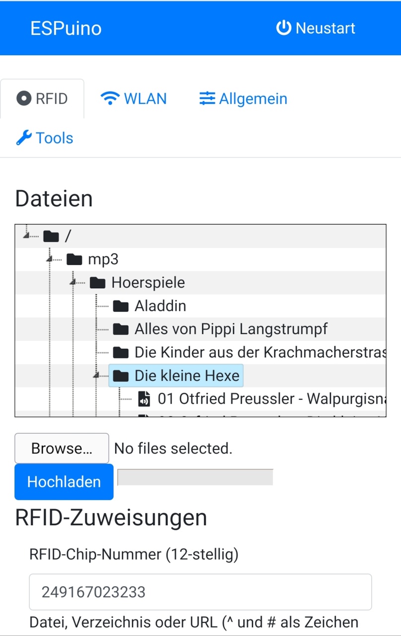
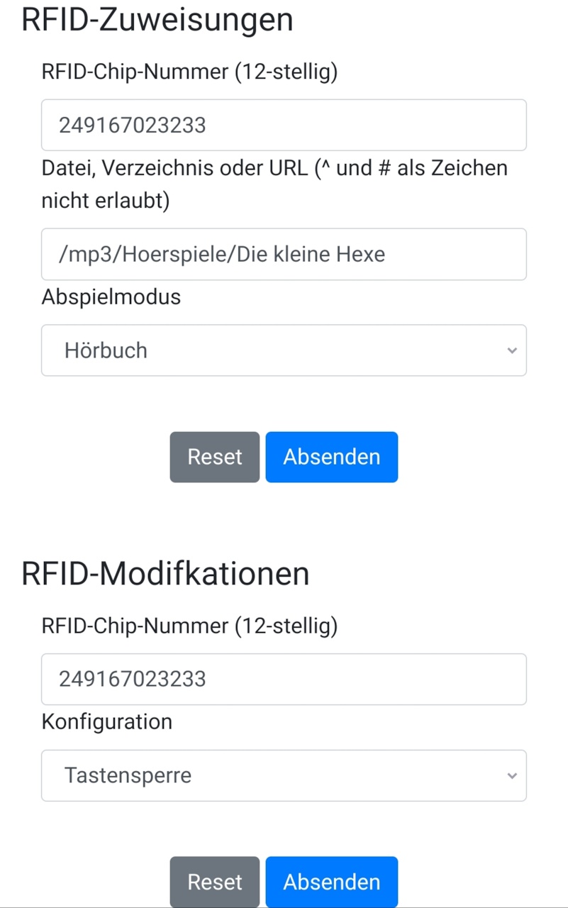
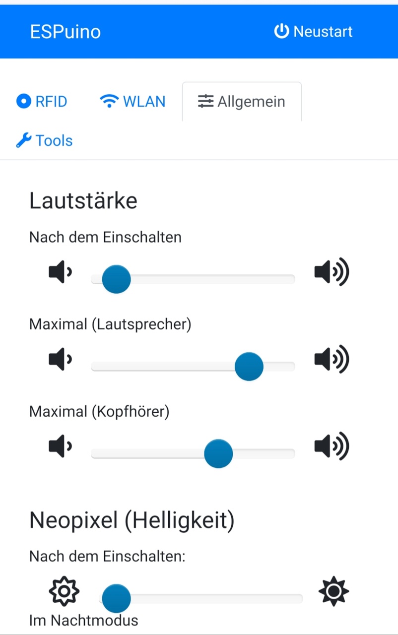
After bringing ESPuino part of your LAN/WiFi, the 'regular' webgui is available at the IP assigned by your router (or the configured hostname). Using this GUI, you can configure:
- WiFi
- Binding between RFID-tag, file/directory/URL and playMode
- Binding between RFID-tag and a modification-type
- MQTT
- FTP
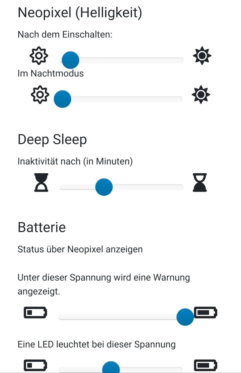
- Initial volume, maximum volume (speaker / headphone), brightness of Neopixel (nightmode / default) and inactivity-time
Webgui #1:
Webgui #2:
Webgui #3:

Webgui #4:
Webgui #5:
Webgui #6:
Webgui #7:
Webgui: websocket broken:
Webgui: action ok:
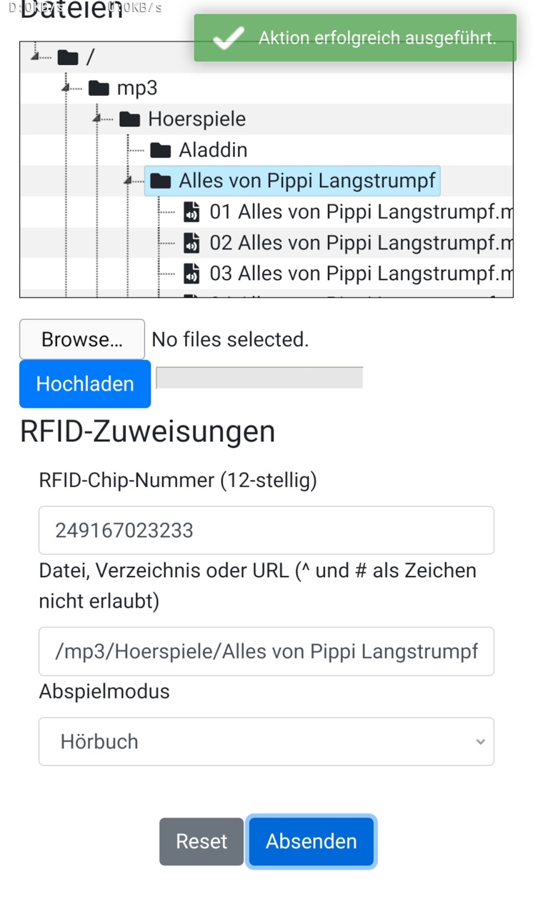
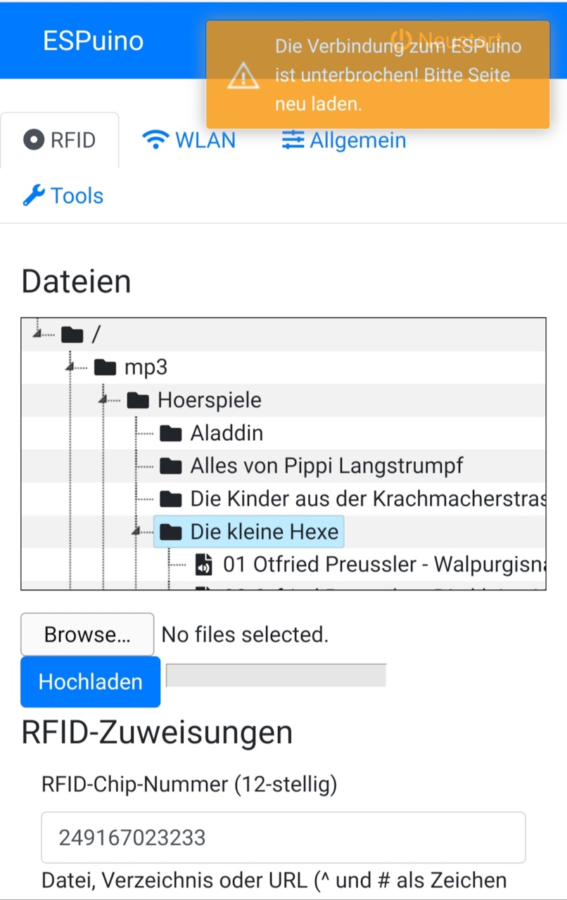
Please note: as you apply a RFID-tag to the RFID-reader, the corresponding ID is pushed to the GUI. So there's no need to enter such IDs manually (unless you want to). Filepath can be filled out by selecting a file/directory in the tree. IMPORTANT: Every time you add, delete or rename stuff on the SD-card, it's necessary to rebuild the json-indexfile. Simply click on the refresh-button below the filetree and wait until it's done. This is because all operations of the filebrowser rely on this file in order to provide a fast way to access all the files and directories.
Interacting with ESPuino
Playmodes
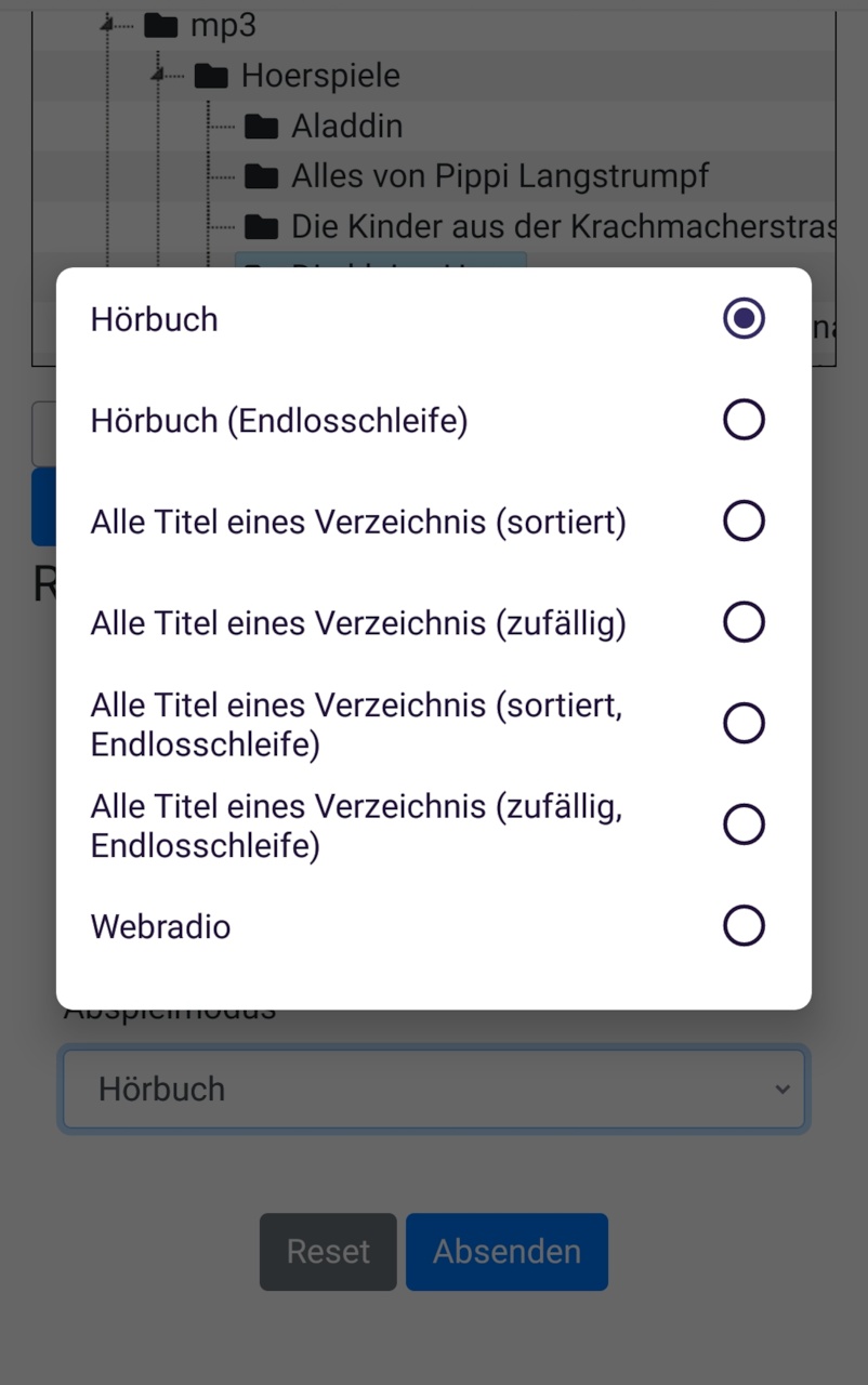
It's not just simply playing music; different playmodes are supported:
-
single track=> plays one track one time -
single track (loop)=> plays one track forever -
audiobook=> single file or playlist/folder; last play-position (file and playlist) is saved (when pushing pause or moving to another track) and re-used next time -
audiobook(loop) => same as audiobook but loops forever -
folder/playlist (alph. sorted)=> plays all tracks in alph. order from a folder one time -
folder/playlist (random order)=> plays all tracks in random order from a folder one time -
folder/playlist (alph. sorted)=> plays all tracks in alph. order from a folder forever -
folder/playlist (random order)=> plays all tracks in random order from a folder forever -
webradio=> always only one "track": plays a webstream
Modification RFID-tags
There are special RFID-tags, that don't start music by themself but can modify things. If applied a second time, it's previous action/modification will be reversed. Please note: all sleep-modes do dimming (Neopixel) automatically because it's supposed to be used in the evening when going to bed. Well, at least that's my children's indication :-) So first make sure to start the music then use a modification-card in order to apply your desired modification:
- lock/unlock all buttons
- sleep after 5/30/60/120 minutes
- sleep after end of current track
- sleep after end of playlist
- sleep after five tracks
- dimm neopixel
- current track in loop-mode (is "stronger" than playlist-loop but doesn't overwrite it!)
- playlist in loop-mode
- track und playlist loop-mode can both be activated at the same time, but unless track-loop isn't deactivated, playlist-loop won't be effective
- Toggle WiFi (enable/disable) => disabling WiFi while webstream is active will stop the webstream instantly!
- Toggle Bluetooth (enable/disable) => restarts ESPuino immediately
Neopixel-ring (optional)
Indicates different things. Don't forget configuration of number of LEDs via #define NUM_LEDS
- While booting: every second LED (rotating orange)
- Unable to mount SD: LEDs flashing red (will remain forever unless SD-card is available or
SHUTDOWN_IF_SD_BOOT_FAILSis active) - IDLE: four LEDs slow rotating (white if WiFi enabled; green if WiFi disabled)
- BLUETOOTH: four LEDs slow rotating coloured blue
- ERROR: all LEDs flashing red (1x) if an action was not accepted
- OK: all LEDs flashing green (1x) if an action was accepted
- BUSY: violet; four fast rotating LEDs when generating a playlist. Duration depends on the number of files in your playlist.
- track-progress: rainbow; number of LEDs relative to play-progress
- playlist-progress: blue; appears only shortly in playlist-mode with the beginning every new track; number of LEDs relative to progress
- webstream: two slow rotating LEDs that change their colours rainbow-wise as the stream proceeds
- volume: green => red-gradient; number of LEDs relative from current to max volume
- switching off: red-circle that grows until long-press-time is reached
- buttons locked: track-progress-LEDs coloured red
- paused: track-progress-LEDs coloured orange
- rewind: if single-track-loop is activated a LED-rewind is performed when restarting the given track
- (Optional) Undervoltage: flashes three times red if battery-voltage is too low. This voltage-level can be configured via GUI.
- (Optional) Short press of rotary encoder's button provides battery-voltage visualisation via Neopixel. Upper und lower voltage cut-offs can be adjusted via GUI. So for example if lower voltage is set to 3.2 V and upper voltage to 4.2 V, 50% of the LEDs indicate a voltage of 3.7 V.
Please note: some Neopixels use a reversed addressing which leads to the 'problem', that all effects are shown
counter clockwise. If you want to change that behaviour, just enable NEOPIXEL_REVERSE_ROTATION.
Buttons
Important: this section describes my default-design: 3 buttons + rotary-encoder. Feel free to change button-number and button-actions according your needs in settings.h and your develboard-specific config-file (e.g. settings-lolin32.h). At maximum you can activate five buttons + rotary-encoder.
Minimum duration for long press in ms is defined by intervalToLongPress.
- previous (short): previous track / beginning of the first track if pressed while first track is playing
- previous (long): first track of playlist
- next (short): next track of playlist
- next (long): last track of playlist
- pause/play (short/long): pause/play
- rotary encoder (turning): vol +/-
- rotary encoder (button long): switch off (only when on)
- rotary encoder (button short): switch on (when switched off)
- rotary encoder (button short): show battery-voltage via Neopixel (when switched on and
MEASURE_BATTERY_VOLTAGEis active) - previous (long; keep pressed) + next (short) + release (both): toggle WiFi enabled/disabled
Music-play
- Music starts to play right after a valid RFID-tag was applied
- If
PLAY_LAST_RFID_AFTER_REBOOTis active, ESPuino will remember the last RFID applied => music-autoplay (if in doubts don't use this feature). - If a folder should be played that contains many mp3s, the playlist generation can take a few seconds. Please note that a file's name including path cannot exceed 255 characters.
- While playlist is generated Neopixel indicates BUSY-mode.
- After last track was played, Neopixel indicates IDLE-mode.
- In audiobook-mode, last play-position is remembered (position in actual file and number of track, respectively) when a new track begins of if pause-button was hit.
- In webstream-mode the stream will instantly stop if WiFi-status is toggled to disabled. ESPuino will return to idle-mode and wait for new RFID-tag.
Audiobook-mode
This mode is different from the other ones because the last playposition is saved. Playposition is saved when...
- next track starts.
- first/previous/last track requested by button.
- pause was pressed.
- playlist is over (playposition is set back to the first track and file-position 0).
- Please note: last playposition is not saved when applying a new RFID-tag. This is intended because otherwise you woldn't have a possibility to not save it.
Webinterface-configuration
After having ESPuino running on your ESP32 in your local WiFi, the webinterface-configuration is accessable. Using this GUI you can configure:
- Wifi-configuration (Wifi-SSID, Wifi-password, ESPuino's name (for nameserver))
- Link between RFID-tag and corresponding action
- (optional) MQTT-configuration (broker's IP)
- (optional) FTP-configuration (username and password)
- General-configuration (volume (speaker + headphone), neopixel-brightness (night-mode + initial), sleep after inactivity)
- Basic music-control: first, last, previous, next-track; volume +/-; play/pause
FTP (optional)
- FTP needs to be activated after boot! Don't forget to assign action
ENABLE_FTP_SERVERinsettings.hto be able to activate it! Neopixel flashes green (1x) if enabling was successful. It'll be disabled automatically after next reboot. Means: you have to enable it every time you need it (if reboot was in between). Sounds annoying and maybe it is, but's running this way in order to have more heap-memory available (for webstream) if FTP isn't running. - In order to avoid exposing µSD-card or disassembling ESPuino all the time for adding new music, it's possible to transfer music to the µSD-card using FTP.
- Default-user and password are set to
esp32/esp32but can be changed later via GUI. - Make sure to set the max. number of parallel connections to ONE in your FTP-client and the charset to CP437. CP437 is important if you want to use german umlauts (öäüß).
- Secured FTP is not available. So make sure to disable SSL/TLS.
- Software: my recommendation is Filezilla as it's free and available for multiple platforms.
- Don't expect a super fast data-transfer; it's around 185 kB/s (SPI-mode) and 310 kB/s (MMC-mode).
- Please note: if music is played in parallel, this rate decrases dramatically! So better stop playback when doing a FTP-transfer.
Energy saving
As already described in the modify-section, there are different sleepmodes available. Additionaly µC will be put into deepsleep after 10 minutes of inactivity (configurable my maxInactivityTime) unless ESPuino doesn't play music, has a FTP-client connected and any input via buttons. Every button-interaction resets the counter.
MQTT (optional)
Everything that can be controlled via RFID-tags and buttons, can also be controlled via MQTT (excepting toggling WiFi-status as this doesn't make sense). All manual interactions (buttons, RFID-tags) are also sent to MQTT in parallel, so everything is always in-sync (unless Wifi/MQTT-connection is broken). In my home-setup I'm using openHAB to "encapsulate" MQTT into a nice GUI, that's accessible via APP + web. I described a sample-config for openHAB2. However, meanwhile openHAb3 is available and all the stuff described can also be configured via GUI. Be advised that openHAB is pretty complex and you have to spend some time to get familiar with it.
Supported file/stream-types
Please refer ESP32-audioI2S, as this is the library I used for music-decoding. Make sure to update especially this library regularly as it's development is still in progress.
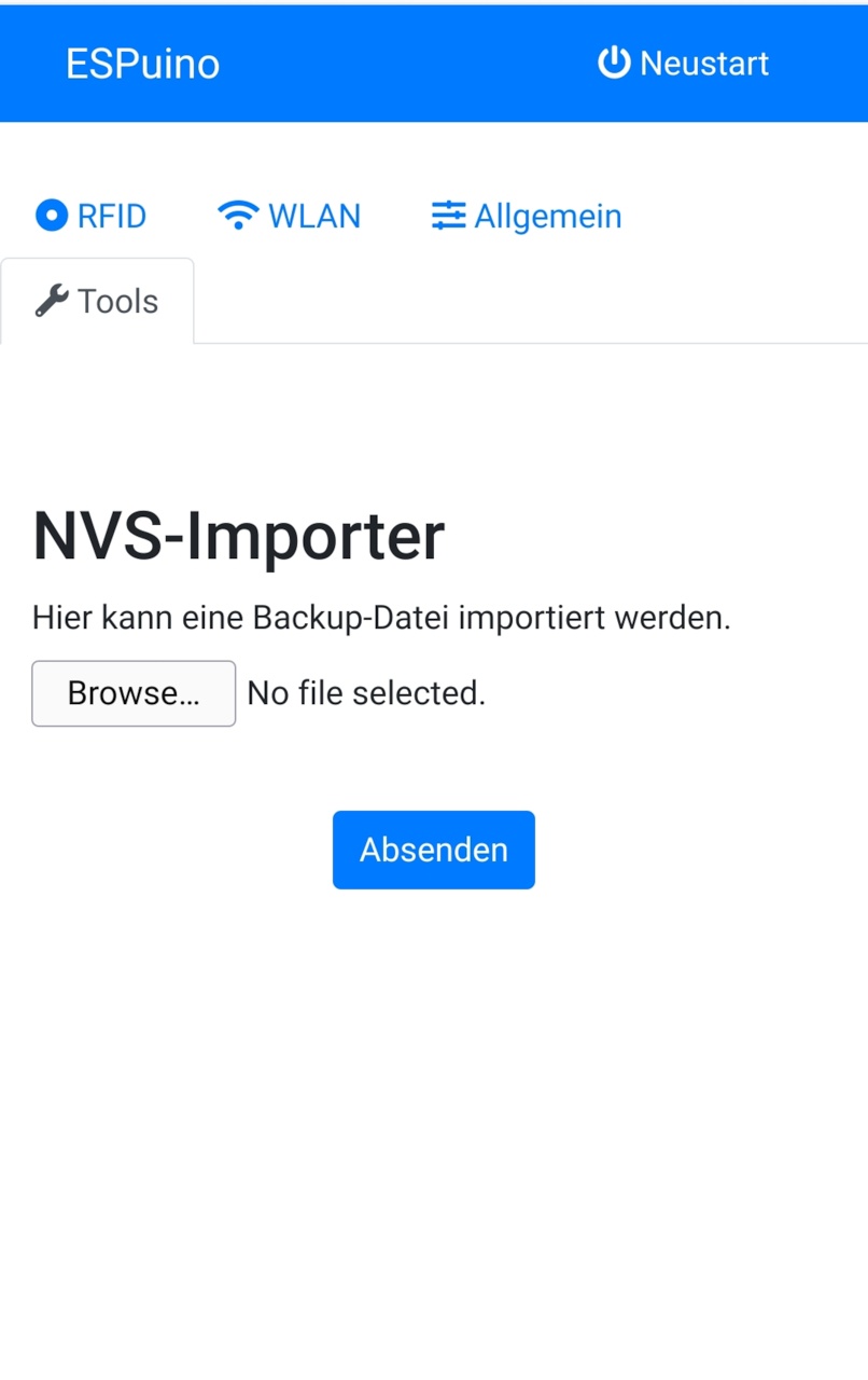
Backups
As all assignments between RFID-IDs and actions (playmode, file to play...) is saved in ESP's NVS, the problem is that it's all gone when the ESP is broken. So that's where a backup comes into play. So every time you change or add a new assignment between a RFID-tag and an action via GUI, a backup-file is saved on the µSD-card. The file's name can be changed via backupFile. So better don't delete it! Using the webgui you can use the upload-form to import such a file. To be honest: Sometimes I had some issues with Firefox doing this whereas Safari turned out to do it right. Don't know why :-(.
Smarthome (optional)
As already described, MQTT is supported. In order to use it it's necessary to run a MQTT-broker; Mosquitto for instance. After connecting to it, ESPuino subscribes to all command-topics. State-topics are used to push states to the broker in order to inform others if anything changed (change of volume, new playlist, new track... name it). Others, like openHAB, subscribe to state-topics end send commands via command-topics. So it's not just limited to openHAB. It's just necessary to use a platform, that supports MQTT. For further informations (and pictures) refer the subfolder.
MQTT-topics and their ranges
Feel free to use your own smarthome-environments (instead of openHAB). The MQTT-topics available are described as follows. Please note: if you want to send a command to ESPuino, you have to use a cmnd-topic whereas ESPuino pushes its states back via state-topics. So guess you want to change the volume to 8 you have to send this number via topic-variable topicLoudnessCmnd. Immediately after doing to, ESPuino sends a conformation of this command using topicLoudnessState. To get hands on MQTT I recommend this one as introducton (covers more than you need for ESPuino).
| topic-variable | range | meaning |
|---|---|---|
| topicSleepCmnd | 0 or OFF | Power off ESPuino immediately |
| topicSleepState | ON or OFF | Sends ESPuino's current/last state |
| topicRfidCmnd | 12 digits | Set number of RFID-tag which 'emulates' an RFID-tag (e.g. 123789456089) |
| topicRfidState | 12 digits | ID of current RFID-tag (if not a modification-card) |
| topicTrackState | String | Sends current track number, total number of tracks and full path of curren track. E.g. "(2/10) /mp3/kinderlieder/Ri ra rutsch.mp3" |
| topicTrackControlCmnd | 1 -> 7 |
1=stop; 2=unused!; 3=play/pause; 4=next; 5=prev; 6=first; 7=last |
| topicLoudnessCmnd | 0 -> 21 | Set loudness (depends on minVolume / maxVolume) |
| topicLoudnessState | 0 -> 21 | Sends loudness (depends on minVolume / maxVolume |
| topicSleepTimerCmnd | EOP | Power off after end to playlist |
| EOT | Power off after end of track | |
| EO5T | Power off after end of five tracks | |
| 1 -> 2^32 | Duration in minutes to power off | |
| 0 | Deactivate timer (if active) | |
| topicSleepTimerState | various | Sends active timer (EOP, EOT, EO5T, 0, ...) |
| topicState | Online, Offline |
Online when powering on, Offline when powering off |
| topicCurrentIPv4IP | IPv4-string | Sends ESPuino's IP-address (e.g. 192.168.2.78) |
| topicLockControlsCmnd | ON, OFF | Set if controls (buttons, rotary encoder) should be locked |
| topicLockControlsState | ON, OFF | Sends if controls (buttons, rotary encoder) are locked |
| topicPlaymodeState | 0 - 10 | Sends current playmode (single track, audiobook...; see playmodes) |
| topicRepeatModeCmnd | 0 - 3 | Set repeat-mode: 0=no; 1=track; 2=playlist; 3=both |
| topicRepeatModeState | 0 - 3 | Sends repeat-mode |
| topicLedBrightnessCmnd | 0 - 255 | Set brightness of Neopixel |
| topicLedBrightnessState | 0 - 255 | Sends brightness of Neopixel |
| topicBatteryVoltage | float | Voltage (e.g. 3.81) |