cnlohr / Wiflier
Labels
Projects that are alternatives of or similar to Wiflier
wiflier, An ESP8266-based Quadcopter Brain
WARNING: This project is still in its early stages! It doesn't fly yet!
WARNING: Everything surrounding a control loop in control.c for flight IS SUPER JANKEY AND TOTALLY NOT HOW IT SHOULD BE!
WARNING: When I operated the PWM at 3kHz, I had to modify my current board to add pullups on the I2C and short out the AVR's reset to VBat, otherwise it seemed to reboot randomly during flight.
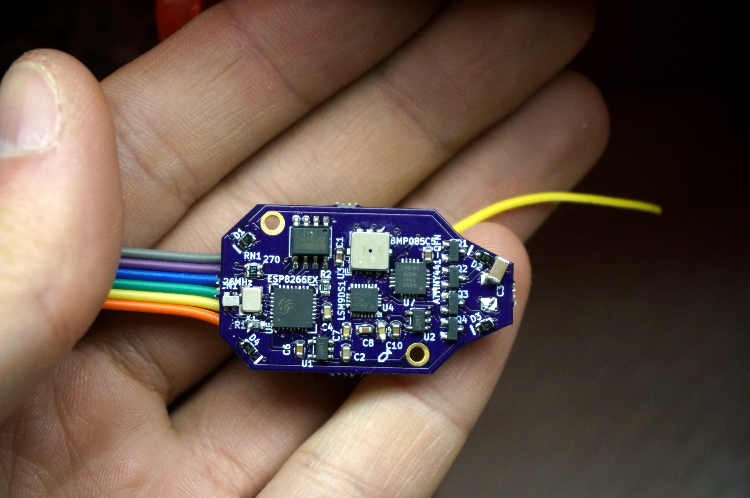
Do you think quadcopters are neat? Eh, not really for me... BUT I THINK ESP8266's ARE AWESOME! So, I slapped an LSM9DS1 IMU, a BMP085 barometer and an AVR co-processor with 4 PWM output drivers to a PCB small enough to fit in a hubsan X4 quadcopter.
Picture of the wiflier brain
Youtube video of the first crack at this:
!(http://img.youtube.com/vi/3n76iMTHXuE/0.jpg)
The Hardware
There is an ESP8266, a 32-bit 80(or 160)MHz processor with 802.11bgn networking at the heart of the system. This run all the user interface code, and handles all control algorithms. It is attached to a 2 MByte flash for code and data storage. It is connected via a software i2c bus to:
- An ATTiny441 with 4 PWM outputs and battery voltage monitoring.
- 4 6-amp N-channel fets, with diode proection on the AVR's output channels to drive DC motors.
- Safe-mode, which ramps PWM down after periods of inactivity.
- A LSM9DS1, 9-axis IMU with temperature sensor. It has a gyro, accelerometer, and magnetometer built in.
- A BMP085, barometer with high precision temperature sensor built in.
Network connectivity
The wiflier uses an ESP8266, which can act as either a station (mode 1) or a softap (mode 2). Softap means it broadcasts a SSID that other compuers can connect to.
Station (Mode 1)
Station mode can be initialized by the W1:[ssid]:password command. This will cause the wiflier to connect to the specified network. It supports WEP, WPA-PSK, and WPA2-PSK. It will remember this setting when it boots up. If it fails to connect, it will revert to mode 2. Currently (maybe?) if it reverts to mode 2, it will stay in mode 2 every subsequent bootup.
If it succeeds in negotiating, it will pull a DHCP lease and print to the serial terminal what that DHCP release is. All communicat
Soft AP (Mode 2)
Soft AP mode allows the ESP8266 to create its own wifi network that you can connect to with a wifi-enabled device. In this mode, one can connect to the new network, and visit the ESP at 192.168.4.1.
This is the default mode.
Command Interfaces
There are currently two command interfaces to the wiflier. One is UDP, on port 7777, the other is via HTTP at http://[ip]/d/issue?.
The UDP interface
For the UDP interface, you can use netcat or 'nc' to communicate with the ESP. This is partciularly convenient as a command-line tool. You can type
nc [ip] 7777 -u
To open a terminal to the wiflier. You can type T1 and enter. This should provide a constant stream of telemetry.
When using the UDP interface, you must only have one command per packet. Packets are the delineation of commands.
The HTTP interface
If you make an HTTP request to http://[ip]/d/issue?[command] where [ip] is the address of the wiflier, and [command] is the command you are issuing, the command will be executed and its return value is sent. You can check this interface's functionality by going to http://192.168.4.1/d/issue?T0 and verify it returns a T0 confirmation. Anything after the question mark will be urldecoded. Things like amphersands should be URL encoded.
The websockets interface.
This interface does not yet exist, but I hope to make it a reality.
Building
This code is separated into two pieces, the ESP firmware and the AVR firmware.
The ESP firmware requires the esp_iot_sdk_v1.1.0, and a copy of the ESP8266 GCC toolchain. To build the ESP firmware, cd to the espfirmware folder and type 'make'.
The AVR firmware requires avr-libc-1.8.0 and avr-gcc-4.8.1 at a minimum. To build the AVR firmware, cd to the avr folder, and type 'make'.
Memory layout:
We use a bit of a modified take on the old memory layout since, while we support OTA upgrades, we do so in a different way than the normal way.
| Address | Size | Name / Description |
|---|---|---|
| 00000h | 64k | 0x00000.bin, IRAM Code |
| 10000h | 180k | Normally unused, HTTP may be here if signature found. |
| 3C000h | 4k | May be used by web interface |
| 3D000h | 4k | our device configuration |
| 3E000h | 8k | May be used by ESP SDK. |
| 40000h | 240k | 0x40000.bin, Cached code. |
| 7C000h | 8k | May be used by ESP SDK. |
| 7E000h | 8k | May be WiFi configuration |
| 80000h | 512k | Scratchpad (Temp only!) |
| 100000h | 1M+ | HTTP data, 1M on W25Q16. HTTP Used here if signature found. |
Hardware designs
The wiflier schematics and PCB layout is done in KiCad (2013-07-03). It should be compatible with newer versions, but is unlikely to be compatible with older versions. In the hardware/ folder, you'll also find wiflier.lst. This contains the part identifier, name, digikey part number (if applicable) and cost assuming an order of ~10 boards.
wiflier UART
The UART on the wiflier is used to send debugging information. The Wiflier does not currently accept commands via the UART. I intend to make the UART available to GPS or video input.
UART flashing the ESP8266.
To UART flash the ESP8266 you will need esptool.py and a serial TTL uart. USB to serial converters are good. Do not use RS-232-level UARTs. To flash this, you will need to:
-
De-power the device.
-
Connect GPIO0 to GND.
-
Connect TX, RX and GND (And possibly power) to your UART, reversing TX/RX lines.
-
Apply power to the device.
-
Then go to the espfirmware folder, and type:
~/esp8266/esptool/esptool.py --port /dev/ttyUSB0 write_flash 0x00000 0x00000.bin 0x40000 0x40000.binor
make burn -
The esptool should reboot into the running code.
Net flashing the ESP8266.
Net Flashing the ESP8266 is particularly easy. Connect to the wiflier, verify you can communicate to it (via HTTP or ping). Use the 'execute_reflash' tool with the following commands:
web/execute_reflash 192.168.4.1 0x00000.bin 0x40000.bin
or, from the espfirmware folder...
make netburn
This will connect to 192.168.4.1, and it will perform the following steps:
- It will attempt to erase the blocks that need to be written (to 0x00000.bin) using the "FB" command.
- And await confirmation.
- It will write the data (0x00000.bin) using the "FW" command.
- And await confirmation.
- It will write this first file to 80000h, then it will repeat for the second file, to c0000h.
- It will then compute the MD5 of the files and execute the "FM" command.
- Internally, the wiflier will verify the integrety of the written files.
- At this point, it will disable all interrupts. Network will go down, etc.
- It will copy the data from 80000h to 00000h, and then copy c0000h to 40000h.
- It will then reboot itself and boot into the new code.
- If a network wasn't found, and it switches to being its own AP... next boot, it should still try to join the old network.
Flashing the AVR
The AVR is particularly easy to flash. You'll need:
- An ISP Programmer, like the TinyISP that operates a 3.3V outputs.
- Under NO condition use a programmer that haves 5V outputs. This will almost certainly cause severe damage to the wiflier.
- Associated 6-pin ISP programming connector.
- AVRDude, or other ISP programming software.
- A 6-pin male-male connector, SMD preferred.
To flash, follow the following steps:
- Connect to a wiflier command interface.
- Use the "B0" command to make the ESP8266 release the bus. * Failure to do this may damage the AVR or ESP.
- Plug the 6-pin male connector into the programming header on the programmer.
- Hold the 6-pin connector on the back of the PCB. * Reversing the order will not program, but will not damage the part. * You can determine proper order by unplugging power to the quadcopter and flipping the connector around until it powers on. Powering on indicates proper order.
- Initiate programming of the AVR. * Failures may indicate the ESP is locking the bus lines. * Failures may indicate not all the pins are making contact. * Failures may indicate the programming header is reversed. * Failures may indicate other problems in the toolchain, i.e. not running programmer as root or having proper credentials.
- Remove programmer.
- Use the "B1" command to bring the ESP8266 Back online.
TODO
Software modifications:
- Try one-shotting the sensors (currently they're in free-run) this will synchronize them to the system clock.
- Try making the system switch over to calling the control loop on interrupt after connection is negotiated, rather than using flags and the idle loop.
- Add WebSockets?
- Add WebGL?
- Separate the control.c into different parts.
- Have some minimal levels of protection for writing to flash, i.e. maybe only allow writing to 0x80000+
- Send some sort of broadcast or discovery packets.
- Figure out why the AVR needs soooo many bytes before it accepts data.
Hardware modifications:
- Consider making the sensors slaves to the AVR, and having the ESP communicate only to the AVR.
- Consider using the MPL3115A2 instead of the BMP085
- I keep looking at the lack of pullups on the I2C and it makes me nervous when we're running the motor controllers.
Commands
The heart of the wiflier is the command engine. This command engine is human-readable, and with the exception of some use cases of the flashing commands is human-readable.
Commands are very simple, they are basically single letters, then parameters, separated by colons. Responses are usually similar to the command that was sent. A failure can be indicated by either a lack of response, or an exclaimation point (!) prefixing the response.
As a warning, in some places \r\n is used and in others \n is used. You should discard \r in all non-binary uses.
Bn (B1 / B0): Turn main control loop on/off
Turning the main control loop off will stop all I2C bus communication and resolving what to do in the control loop. That also means telemetry will stop.
D
Reboot the system. This includes the bootloader. If GPIO0 is held low, the serial bootloader will be initiated.
Tn (T1 / T0): Turn streaming of calibrated, filtered telemetry data on/off
This will either continously stream, or turn off streaming of the calibrated telemetry data from the sensors. Calibration is done using the Rn and Z commands. Data is tab deliniated.
The streaming format is: TD: [frame #] [GyroX] [GyroY] [GyroZ] [AccX] [AccY] [AccZ] [MagX] [MagY] [MagZ] [Pressure in Bar] [Temperature in tenths of degrees C] [battery voltage in 1/100ths of a volt]\n
Un (U1 / U0): Turn streaming of uncalibrated/raw telemtry data on/off
This will enable/disable streaming of uncalibrated telemetry data, straight from the sensors. Data is tab deliniated.
The streaming format is: UD: [frame #] [GyroX] [GyroY] [GyroZ] [AccX] [AccY] [AccZ] [MagX] [MagY] [MagZ] [Pressure in Bar] [Temperature in tenths of degrees C] [battery voltage in 1/100ths of a volt]\n
For example:
UD   9224      600      199      137     2839     1790     2080       61     2214    -4673    101233    368    499 \r\n
UD   9225     -616     -244      304     3208     1797     1934       40     2229    -4673    101233    368    507 \r\n
UD   9226     -687     -234      318     3374     1815     1893       74     2259    -4683    101233    368    507 \r\n
UD   9227      242      240       43     2960     1795     2051       31     2223    -4691    101233    368    507 \r\n
UD   9228      455      146       46     3122     1708     1964       37     2226    -4664    101237    368    507 \r\n
Z: Set 'zero'
Sending a Z will set the zero all gyros, and accelerometer X and accelerometer Y. This will only have an effect on the calibrated, filtered telemetry data.
Rn (R1 / R0): Enable range calibration.
When you want to begin range calibration (for accelerometer Z, and all mag inputs) send R1. This will begin to look for peak positive and negative values. When you execute R0, it will take whatever the maximums are and scale all data to that range.
P: Print calibration and other system data.
When you send a 'P' command, the wiflier will send back all calibration and possibly other system data. As of the time of writing this the following values are returned:
    P6
    #GC\t x \t y \t z (Gyro Zero)
    #AC\t x \t y \t z (Accelerometer Zero)
    #AL\t x \t y \t z (Accelerometer Minimum)
    #AM\t x \t y \t z (Accelerometer Maximum)
    #ML\t x \t y \t z (Magnetometer Minimum)
    #MH\t x \t y \t z (Magnetometer Maximum)
S: Save calibration and other settings.
This writes the current information in the global settings value to the flash at address 3D000h.
Mx: Motor control functions
M?: Motor query
Returns if motors are in automatic mode (1/0) and all motor speeds, 0..255 speed.
M? will return `M?[automatic]:[M0 speed]:[M1 speed]:[M2 speed]:[M3 speed]\r\n"
MA: Motors in automatic mode
Selecting this function will move the move the motors into automatic mode, allowing a control algorithm to take them over.
(Not currently implemented)
MM: Motors in manual mode
Disable automatic control of motors, they will now respond to the M(number) commands. Optionally, can take up to 4 arguments for the new motor set values.
M0, M1, M2, M3: Set motor speed.
If you want to control an individual motor speed, you call Mn:speed for example M0:127 would turn motor 0 on to half duty cycle. This only works if the motors are in manual mode.
Fx: Flash commands
FEn: Flash Erase Sector
Erase a specific flash sector, it will erase the flash starting at address n4096 to n4096+4095. This function works with flash memory below and above the 1MB barrier, however it takes a moment to execute and no interrupts may run while it is executing.
FBn: Flash Erase Block
Erase a specific block of flash. This operates on a whole 64kB block, and takes about as long as it takes FE to erase just one sector. This function does not work past the 1MB barrier.
FW: Flash Write
This function writes flash. It requires two parameters, the first is the starting addres, the second is the size (in bytes). Writes must be aligned to 4-byte boundaries, sizes must line to 4-byte boundaries.
FW40:8:hello\r\n
Will write hello\r\n\0 to memory address 40 (which will break booting, so don't do this), and it will respond with:
FW40
FR: Flash Read
This will read back from the flash, starting at the first parameter and with length of the second.
FR40:8\r\n
Will read from address 40 8 bytes and if we've executed the terrible terrible example above, respond with:
FR00000040:0008:hello\r\n\0
FM: Rewrite boot flash
This function takes several parameters, in the style: FMa🅱️c:d:e:f:g:h where
- A = Address to copy from #1
- B = Address to copy to #1 (Must be 65kB aligned)
- C = Number of bytes to copy #1 (Must be 1k chunks)
- D = MD5 of entire 'from #1' range.
- E = Address to copy from #2
- F = Address to copy to #2 (Must be 65kB aligned)
- G = Number of bytes to copy #2 (Must be 1k chunks)
- H = MD5 of entire 'from #2' range.
This will verify both MD5's before copying. Interrupts will continue to execute until the actual flash-over begins. Once flash-over is complete, the device will automatically reboot.
An example would be:
FM524288:0:33792:d6f04e459bc9aefabd9ed80981e6837f:786432:262144:171008:8435d1904110eacb66771320f63736bc
It should respond with FM In the event of a failure, it will also send a !FM[code].
Wx: Wireless/Network commands.
W1: Connect to wifi network.
If you want to connect to an existing wifi network, you can use the W1 command. This will find the specified AP, and join. An example W1 command would be W1:ssid:password. This will connect to network with name 'ssid', and password 'password'. If it fails to connect, it will switch back to softap mode.
W2: Make softAP network
This will cause the ESP8266 to make its own network. You can connect to it. Its IP will be 192.168.4.1
WI: Get current settings
This will cause the ESP8266 to give you the mode (1 or 2) SSID, and password of the current network status.
For example WI will return WI1:mynetwork:mypassword.
WS: Scan for networks
WARNING: If operating in mode 2, this will cause the ESP to go offline momentarily while it scans!
If you issue the WS command, the ESP8266 will begin a scan. It is unlikely to return any response at all. You can read the returned networks with the WR command.
It may take several seconds for the WS command to complete.
WR: Return wireless networks from last scan.
After you scan for networks, you can probe for responses to those networks with the WR command. It returns WRn where n is the number of networks found. It will then provide the networks in a tab delinated data format as follows:
#SSID MAC RSSI Channel Encryption
For example a response to the WR command could be:
WR3
#quiddles       00:23:15:11:22:41       -44     1       open
#reads          08:18:a0:02:4d:cc       -55     1       wpa2
#rguest         0a:14:c1:f3:02:a0       -68     11      open
J: Joystick commands
SECTION NOT WRITTEN