TinyCharger - Single Cell Li-Ion Battery Charger with Monitoring
TinyCharger is an ATtiny25/45/85-based, single-cell Li-ion battery charger with selectable charging current limit (100mA - 1000mA) and an OLED display for monitoring.
- Project Video (Youtube): https://youtu.be/JtS_8n5oOiI
- Design Files (EasyEDA): https://easyeda.com/wagiminator/attiny85-lipo-charger
Hardware
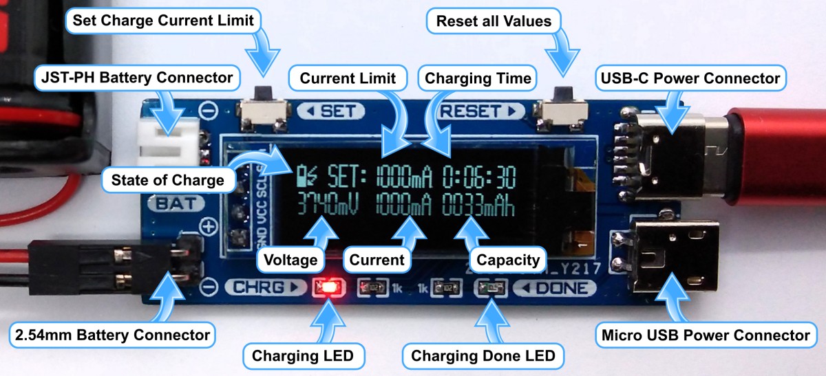
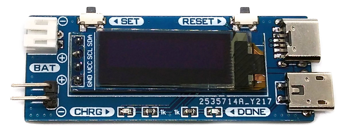
Power Connectors
The device is equipped with a Micro-USB and a USB-C connector for power supply. Only one connector can be used at a time. The supply voltage must be 5V.
Battery Connectors
The device is equipped with a JST-PH 2.0mm socket and a 2.54mm pin header for connection to the battery. Only one battery can be charged at a time.
Battery Charger
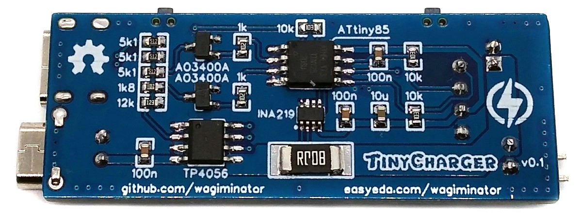
For battery charging the TP4056 is used. The TP4056 is a complete constant-current/constant-voltage linear charger for single-cell lithium-ion batteries. The maximum charge voltage is fixed at 4.2V and the charge current can be programmed externally with a resistor. The total resistance is determined by three resistors connected in parallel, two of which can be switched on and off by the ATtiny via MOSFETs. The TP4056 automatically terminates the charge cycle when the charge current drops to 1/10th the programmed value after the final float voltage is reached. Other features include current monitor, under voltage lockout and automatic recharge.
Voltage and Current Measurement
An INA219 is used to measure voltage and current. The INA219 is a current shunt and power monitor with an I²C-compatible interface. The device monitors both shunt voltage drop and bus supply voltage, with programmable conversion times and filtering. A programmable calibration value, combined with an internal multiplier, enables direct readouts of current in amperes. The selected shunt resistance of 8mΩ enables both a very small influence on the circuit and a measurement with a resolution of 1mA. For an accurate measurement, a shunt resistor with a low tolerance (1% or better) should be selected.
User Interface
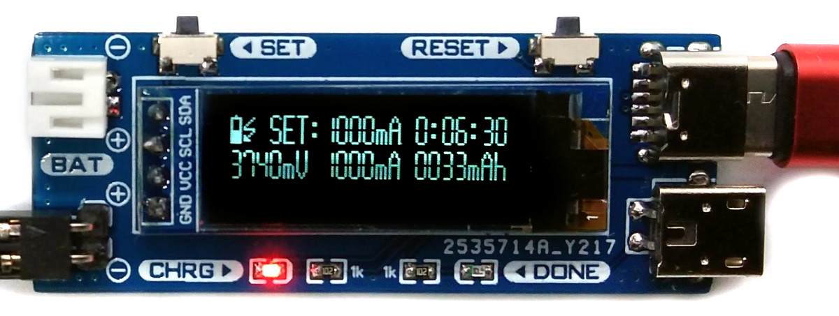
The user interface utilizes two buttons and a 128x64 pixels OLED display. An ATtiny25/45/85 microcontroller handles the user interface as well as the control and monitoring of the charging functions.
Software
Basic Principle
The charging current is programmed via a resistor, the value of which can be set by the ATtiny via two MOSFETs and changed by pressing the SET button. An INA219 continuously measures the charging current and voltage and transmits the values to the ATtiny via I2C. From this, the ATtiny calculates the state of charge and capacity and displays the values on the OLED screen.
I²C OLED Implementation
The I²C protocol implementation is based on a crude bitbanging method. It was specifically designed for the limited resources of ATtiny10 and ATtiny13, but it works with some other AVRs (including the ATtiny25/45/85) as well. The functions for the OLED are adapted to the SSD1306 OLED module, but they can easily be modified to be used for other modules. In order to save resources, only the basic functionalities which are needed for this application are implemented. For a detailed information on the working principle of the I²C OLED implementation visit TinyOLEDdemo.
Accuracy of Time and Capacity Determination
The internal oscillator of the ATtiny is used to determine the charging time and the electric charge. The accuracy of the internal oscillator is +/-10% with the factory calibration. This can be improved to +/-2% or better by manual calibration. The calibration value determined in this way can be set in the source code. In addition to the time measurement, the internal resistance of the battery being charged also plays a role for the accuracy of the calculated capacity. Due to these factors, the displayed capacity is only a rough estimate.
Compiling and Uploading
Since there is no ICSP header on the board, you have to program the ATtiny either before soldering using an SOP adapter, or after soldering using an EEPROM clip. The AVR Programmer Adapter can help with this.
If using the Arduino IDE
- Make sure you have installed ATtinyCore.
- Go to Tools -> Board -> ATtinyCore and select ATtiny25/45/85 (No bootloader).
- Go to Tools and choose the following board options:
- Chip: ATtiny25 or 45 or 85 (depending on your chip)
- Clock: 1 MHz (internal)
- B.O.D.Level: B.O.D. enabled (2.7V)
- Leave the rest at the default settings
- Connect your programmer to your PC and to the ATtiny.
- Go to Tools -> Programmer and select your ISP programmer (e.g. USBasp).
- Go to Tools -> Burn Bootloader to burn the fuses.
- Open TinyCharger sketch and click Upload.
If using the precompiled hex-file
- Make sure you have installed avrdude.
- Connect your programmer to your PC and to the ATtiny.
- Open a terminal.
- Navigate to the folder with the hex-file.
- Execute the following command (if necessary replace "t85" with your chip and "usbasp" with the programmer you use):
avrdude -c usbasp -p t85 -U lfuse:w:0x62:m -U hfuse:w:0xd5:m -U efuse:w:0xff:m -U flash:w:tinycharger.hex
If using the makefile (Linux/Mac)
- Make sure you have installed avr-gcc toolchain and avrdude.
- Connect your programmer to your PC and to the ICSP header of the device.
- Open the makefile and change the chip if you are not using ATtiny85 and the programmer if you are not using usbasp.
- Open a terminal.
- Navigate to the folder with the makefile and the Arduino sketch.
- Run "make install" to compile, burn the fuses and upload the firmware.
Operating Instructions
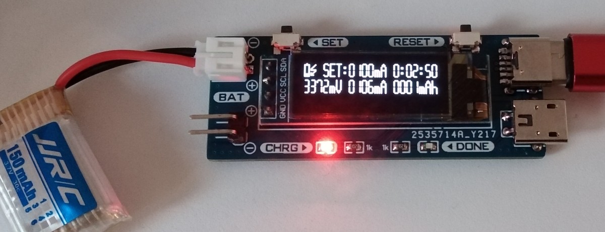
- Connect the device via the Micro-USB or USB-C port to a 5V power supply that can provide sufficient current.
- Use the SET button to select the maximum charging current. Note that it can overshoot by a few milliamperes!
- Connect the Li-Ion battery to one of the battery connectors. Pay attention to the correct polarity!
- The battery is charged immediately. The SET button is locked during the charging process to prevent the charging current from being changed accidentally. The charging process stops automatically when the battery is fully charged. The total charging time and the charged capacity remain displayed as long as the device is supplied with power. These values can be reset using the RESET button.
Characteristics
| Parameter | Value |
|---|---|
| Supply Voltage | 4.3 - 5.5V |
| Charge Voltage Limit | 4.2V |
| Charge Current Limits | 100, 350, 750, 1000mA (selectable) |
| Voltage Measurement Resolution | 4mV |
| Current Measurement Resolution | 1mA |
References, Links and Notes
License

This work is licensed under Creative Commons Attribution-ShareAlike 3.0 Unported License. (http://creativecommons.org/licenses/by-sa/3.0/)