TinyUPS - Uninterruptible Power Supply based on ATtiny13A
TinyUPS is a simple 5V/2.5A uninterruptible power supply with a li-ion battery as a buffer, a load sharing power path management system and an ATtiny13A for monitoring power supply and battery charge level as well as for communication with the connected device.
- Design Files (EasyEDA): https://easyeda.com/wagiminator/attiny13-tinyups-smd
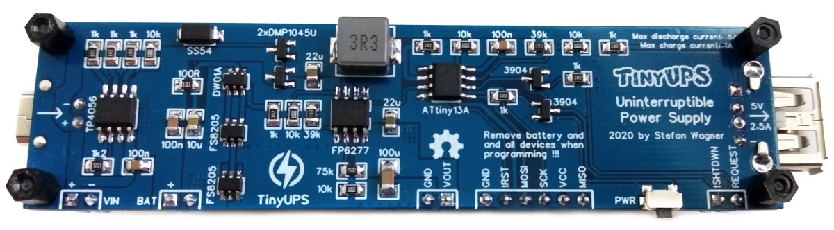
Hardware
The functional principle is shown in the following block diagram:
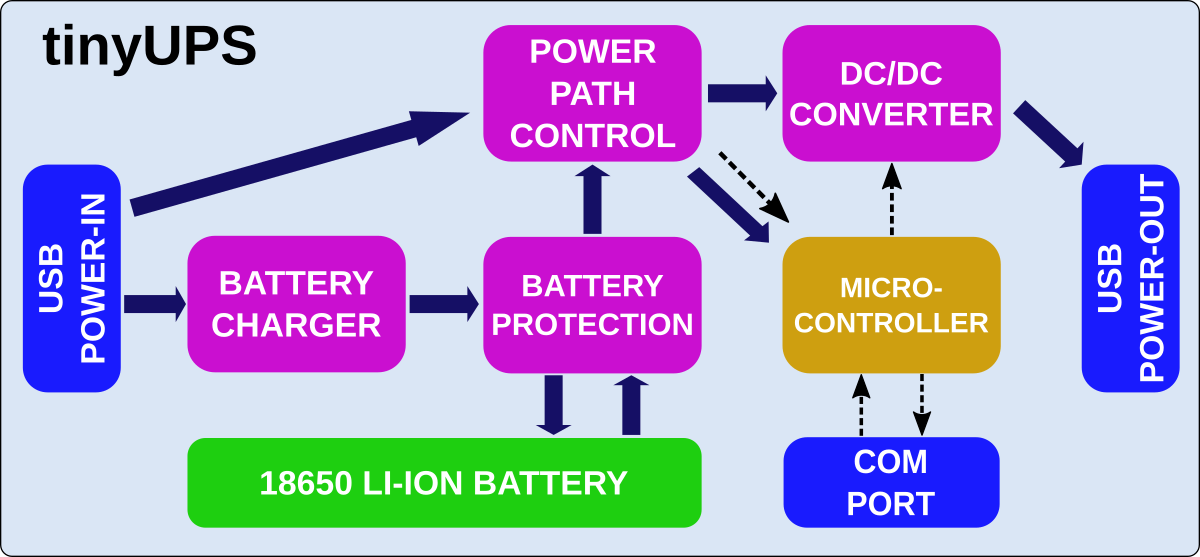
Battery Charger
For battery charging the TP4056 is used. The TP4056 is a complete constant-current/constant-voltage linear charger for single cell lithium-ion batteries. The charge voltage is fixed at 4.2V and the charge current (max 1000mA) can be programmed externally with a single resistor (R3). The TP4056 automatically terminates the charge cycle when the charge current drops to 1/10th the programmed value after the final float voltage is reached. Other features include current monitor, under voltage lockout and automatic recharge.
Battery Protection
For the battery protection (overcharge, overdischarge, overcurrent and short circuit protection) the DW01A is used in combination with two FS8205 dual MOSFETs in parallel. The DW01A is constantly measuring the voltage across the battery and the current flowing in (when charging) or coming out (when discharging). If something goes wrong it takes the battery out of the circuit by closing the MOSFETs which act like a switch between the negative side of the battery (B-) and ground. The overcurrent protection works by comparing the voltage drop across the MOSFET with the internal 150mV reference of the DW01A. As the RDS(on) of one FS8205 is around 2x25mOhm, the DW01A would close the MOSFET at 150mV/50mOhm = 3A if only one FS8205 were used. By using two FS8205 in parallel, the resistance is cut in half, so the DW01A shuts down at 150mV/25mOhm = 6A and one FS8205 must only handle half of the current (3A) which is well within its specs. In this way, up to 6 amps can flow from the battery into the boost converter with a maximum voltage drop of 150mV.
DC/DC Converter
To step up the voltage to 5V the FP6277 low-cost synchronous boost converter is used. Instead of a diode that is used in conventional boost converters, it switches a second built-in MOSFET in sync with the first via the PWM signal. This significantly increases efficiency and thus higher output currents are possible. Note that he EP plate of the FP6277 requires a good conductive connection to the corresponding plate on the PCB.
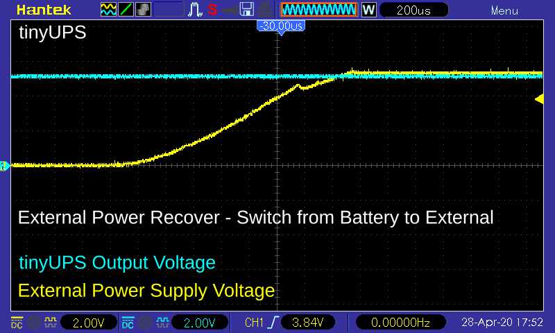
Power Path Control
Although it would be possible to supply the connected device via the battery and charge the battery at the same time, this is absolutely not a recommended way. In this case, most charging ICs such as the TP4056 are unable to determine whether the battery is fully charged because the current never drops below 1/10th of the programmed charging current value which would tell the device to terminate the charging cycle. The battery would be charged forever, which would destroy it in the long run. A load sharing system was therefore integrated, which separates the battery from the load when an external power is present. While the battery is being charged, the connected device is powered by the external power supply. For more details on the working principle of the load sharing power path management circuit refer to Microchip's Application Note 1149.
Microcontroller and COM Port
The ATtiny13A is used for monitoring power supply and battery charge level as well as for communication with the connected device. The ATtiny tells the connected device that it has to shut down by pulling the SHUTDOWN line to LOW. The SHUTDOWN pin of the tinyUPS is an open collector output. The connected device must have an internal or external pullup resistor on the SHUTDOWN line! This is necessary because of the different voltage levels. The connected device can request a shutdown by setting the REQUEST line to HIGH. The REQUEST line can further be controlled via the built-in button.
Software
Firmware for the Microcontroller
The control parameters are defined at the beginning of the code and can be adapted to the needs of the user.
// Control parameters
#define SHUTDOWNLEVEL   3000    // supply voltage threshold in mV for auto shutdown
#define USERPOWERLEVEL  3500    // supply voltage when user is allowed to power on
#define POWERONLEVEL    4300    // supply voltage threshold in mV for auto power on
#define BOOTUPTIMER     60      // time in seconds the connected device needs to boot up
#define SHUTDOWNTIMER   30      // time in seconds the connected device needs to shut down
#define REQUESTTIMER    20      // duration in 100ms request/button has to be low to shut down
If external power is connected to the tinyUPS the input voltage or vcc of the ATtiny13 is delivered by this source, otherwise by the battery. The ATtiny13 monitors the input voltage and tells the connected device to shutdown by pulling the SHUTDOWN-line low when the input voltage falls below a certain threshold (SHUTDOWNLEVEL). This happens when the external power source is diconnected or disabled and the battery level falls below this threshold. After waiting a certain time (SHUTDOWNTIMER) to allow the connected device to safely shut down, the ATtiny13 deactivates the boost converter and turns off the power to the connected device. A shutdown can also be initiated by pressing and holding the button or by setting the REQUEST-line to high (>0.7V) for 2 seconds. After such shutdowns the power will not be turned on again automatically.
// Check if power has to be turned off
while(1) {
  vcc = getVcc();                         // get battery voltage
  if (vcc < SHUTDOWNLEVEL) break;         // shutdown when battery low
  uint8_t counter = REQUESTTIMER;         // timer for manual shutdown
  while((!pinRead(REQUEST)) && (--counter)) _delay_ms(100);
  if (!counter) {autopoweron = 0; break;}
  if (gtimer) gtimer--;                   // decrease boottimer
  sleep(WDT8S);                           // sleep for a while...
}

// Shut down sequence
GIMSK = 0;                                // disable pin change interrupt
pinHigh(SHUTDOWN);                        // tell the device to shutdown now
gtimer = (gtimer << 3) + SHUTDOWNTIMER;   // set timer for shutdown
do {                                      // start timed sequence
  pinToggle(LED);                         // toggle LED
  sleep(WDT1S);                           // sleep one second
} while (--gtimer);
pinLow(SHUTDOWN);                         // release SHUTDOWN pin
GIMSK = (1<<PCIE);                        // pin change interrupts enable

// Turn off power
pinLow(ENABLE);                           // disable boost converter
If the input voltage rises again above a certain threshold (POWERONLEVEL) it activates the boost converter and turns on the power to the connected device. This happens when the external power source is available again. When power is turned on a BOOTUPTIMER starts to count. If a shutdown is initiated before the boot up is completed, the left-over time is added to the SHUTDOWNTIMER in order to allow the connected device to completely boot up and shut down. The power to the connected device can be turned on manually by pressing the button or setting the REQUEST-line to high if the battery level is above a certain threshold (USERPOWERLEVEL) or the external power source is connected.
// Check if power has to be turned on
while(1) {
  pinHigh(LED);                           // heartbeat on status LED
  vcc = getVcc();                         // get supply voltage
  if (autopoweron && (vcc >= POWERONLEVEL)) break;
  if ((!pinRead(REQUEST)) && (vcc >= USERPOWERLEVEL)) break;
  pinLow(LED);                            // turn off status LED again
  sleep(WDT8S);                           // sleep for a while...
}

// Turn on power
pinHigh(ENABLE);                          // set enable pin of boost converter
autopoweron = 1;                          // assume auto power on by now
gtimer = (BOOTUPTIMER >> 3) + 1;          // set timer for bootup
The ATtiny13 spends most of the time in power-down sleep mode to save energy. The watch dog timer wakes it up every 8 seconds. It will also wake up if the button was pressed or the REQUEST-line was changed (pin change interrupt). After doing its stuff the ATtiny13 sleeps again.
// Watch dog timer intervals
#define WDT1S   (1<<WDTIE)|(1<<WDP2)|(1<<WDP1)  // WDTCR value for 1 second
#define WDT8S   (1<<WDTIE)|(1<<WDP3)|(1<<WDP0)  // WDTCR value for 8 seconds

// Reset watchdog timer
void resetWatchdog (uint8_t WDTtime) {
  cli();                                  // timed sequence coming up
  wdt_reset();                            // reset watchdog
  MCUSR = 0;                              // clear various "reset" flags
  WDTCR = (1<<WDCE)|(1<<WDE)|(1<<WDTIF);  // allow changes, clear interrupt
  WDTCR = WDTtime;                        // set interval
  sei();                                  // interrupts are required now
}

// Go to sleep in order to save energy, wake up by watchdog timer or pin change interrupt
void sleep(uint8_t WDTtime) {
  set_sleep_mode(SLEEP_MODE_PWR_DOWN);    // set sleep mode to power down
  GIFR |= (1<<PCIF);                      // clear any outstanding interrupts
  resetWatchdog(WDTtime);                 // get watchdog ready
  sleep_mode();                           // sleep
}

// Watchdog interrupt service routine
ISR (WDT_vect) {
  wdt_disable();                          // disable watchdog
}

// Pin change interrupt service routine
EMPTY_INTERRUPT(PCINT0_vect);             // nothing to be done here
Compiling and Uploading
If using the Arduino IDE
- Make sure you have installed MicroCore.
- Go to Tools -> Board -> MicroCore and select ATtiny13.
- Go to Tools and choose the following board options:
- Clock: 1.2 MHz internal osc.
- BOD: BOD disabled
- Timing: Micros disabled
- Connect your programmer to your PC and to the ICSP header of the TinyUPS board.
- Go to Tools -> Programmer and select your ISP programmer (e.g. USBasp).
- Go to Tools -> Burn Bootloader to burn the fuses.
- Open the TinyUPS sketch and click Upload.
If using the precompiled hex-file
- Make sure you have installed avrdude.
- Connect your programmer to your PC and to the ICSP header of the TinyUPS board.
- Open a terminal.
- Navigate to the folder with the hex-file.
- Execute the following command (if necessary replace "usbasp" with the programmer you use):
avrdude -c usbasp -p t13 -U lfuse:w:0x2a:m -U hfuse:w:0xff:m -U flash:w:tinyups.hex
If using the makefile (Linux/Mac)
- Make sure you have installed avr-gcc toolchain and avrdude.
- Connect your programmer to your PC and to the ICSP header of the TinyUPS board.
- Open the makefile and change the programmer if you are not using usbasp.
- Open a terminal.
- Navigate to the folder with the makefile and sketch.
- Run "make install" to compile, burn the fuses and upload the firmware.
Scripts for the RaspberryPi
How to install tinyUPS for RaspberryPi
- copy all files inside the raspberrypi folder to one folder on the Pi, e.g. /home/pi/tinyUPS
- change GPIO pins for REQUEST and SHUTDOWN in the python scripts if needed
- open a terminal and enter the following commands:
- move to the folder:
cd /home/pi/tinyUPS - make install script executable:
chmod -x install.sh - start install script:
sudo ./install.sh - reboot the Pi:
sudo reboot
How to uninstall tinyUPS for RaspberryPi
- open a terminal and enter the following commands:
- move to location of uninstall.sh:
cd /home/pi/tinyUPS - make uninstall script executable:
chmod -x uninstall.sh - start uninstall script:
sudo ./uninstall.sh - reboot the Pi:
sudo reboot
Operating Instructions
Connections
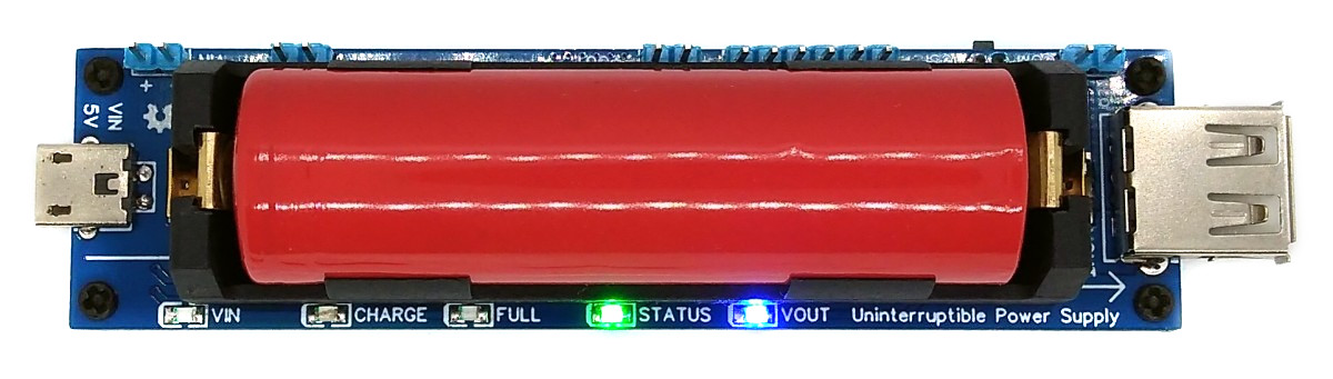
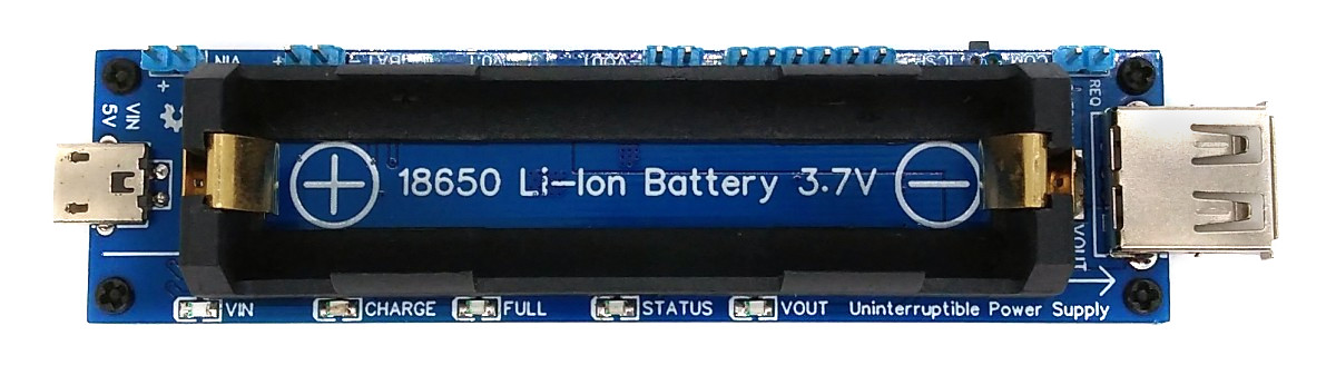
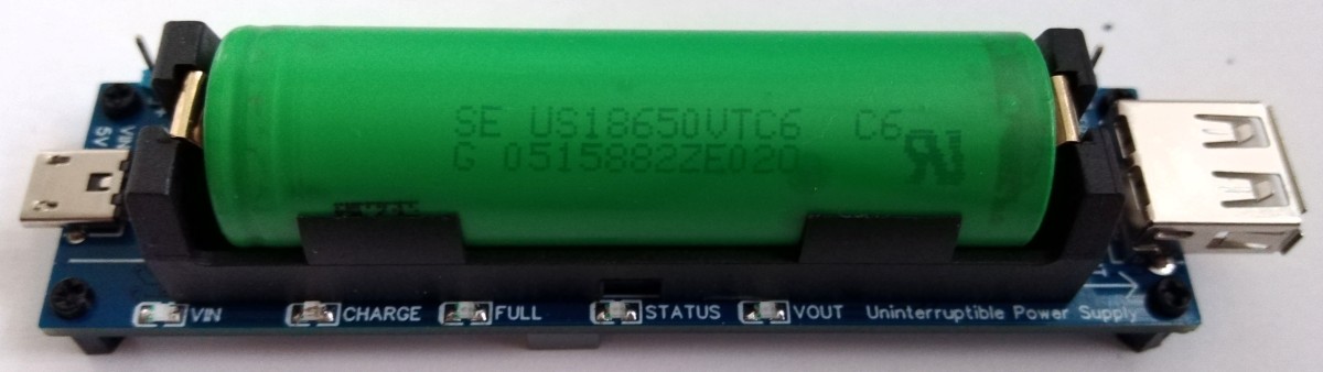
Place an 18650 Li-ion battery in the battery holder. Connect the power supply to the micro-USB port on the TinyUPS. If desired, connect the SHUTDOWN and REQUEST lines to the corresponding pins on the target device. Connect the target device to the USB output of the TinyUPS.
Power Supply Recommendations
External power supply should be capable of delivering enough power to charge the battery and to power the connected device simultaneously. The maximum battery charging current is set to 1000mA but you can set a lower limit by selecting a different value of R3. The output voltage of the external power supply must not exceed 5.2V! Choose a good 18650 Li-Ion battery with a low internal resistance which is capable of delivering up to 6A!
| Parameter | Value |
|---|---|
| Input Voltage | 4.5 - 5.2 V |
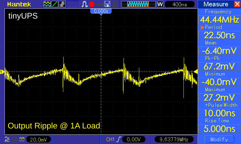
| Output Voltage | 4.8 - 5.2 V |
| Output Current | Max 2.5 A |
| Charging Current | Max 1000 mA |
| Standby Current | 95 uA |
Status LEDs
The current status of the tinyUPS is indicated by 5 LEDs:
| LED | State |
|---|---|
| VIN: on | external power is connected |
| CHARGE: on | battery is charging |
| FULL: on | battery is fully charged (is only shown if external power is connected) |
| STATUS: steady on | normal power-on operation |
| STATUS: blinking | in shutdown sequence |
| STATUS: short flashes | in standby (short flash occurs every 8 seconds) |
| VOUT: on | output power is turned on |
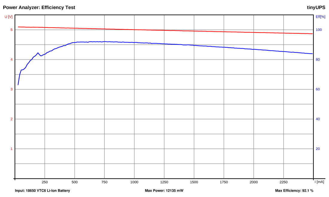
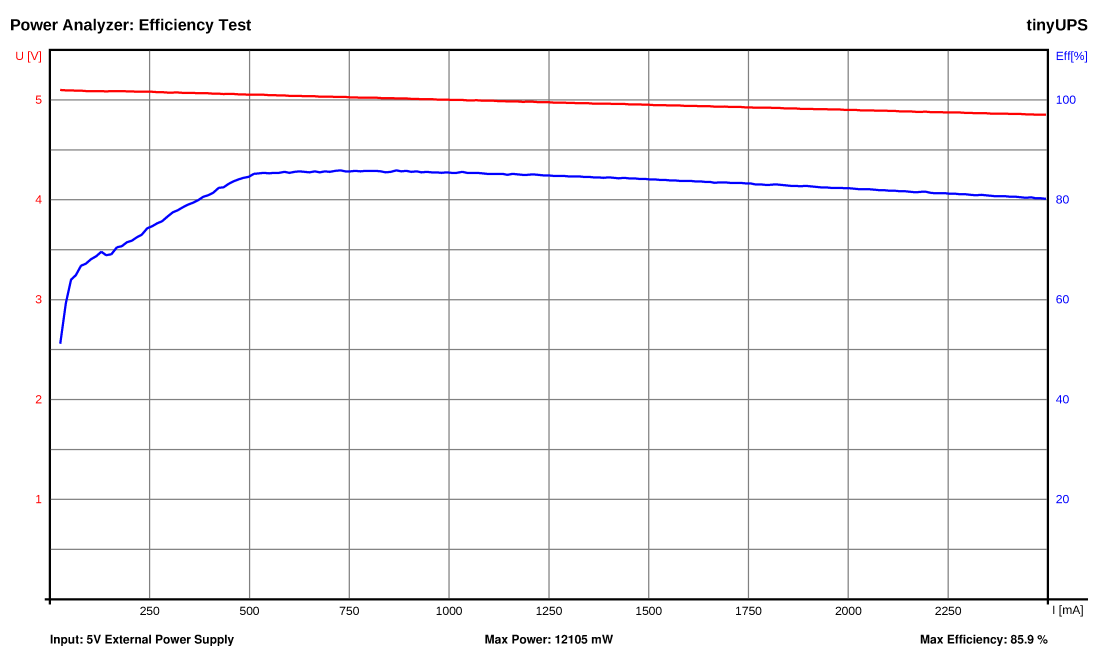
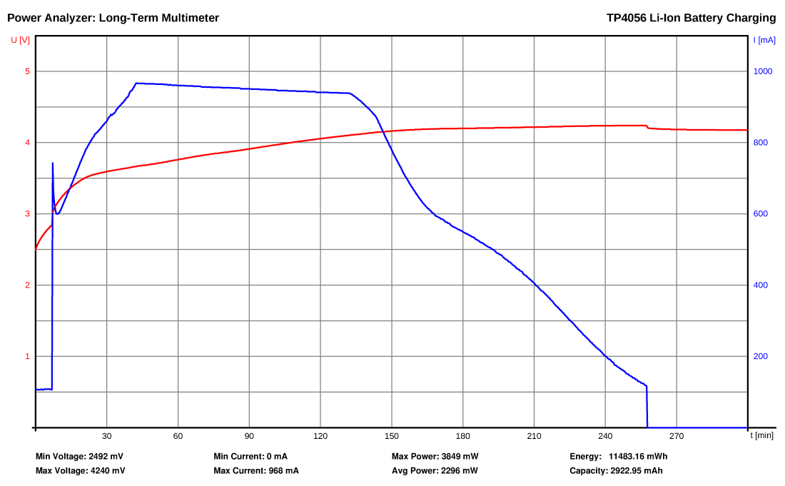
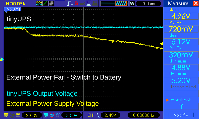
Performance
References, Links and Notes
- ATtiny13A Datasheet
- Microchip's Application Note 1149
- Raspberry Pi Startup Script Tutorial
- Safe Shutdown for RaspberryPi
License

This work is licensed under Creative Commons Attribution-ShareAlike 3.0 Unported License. (http://creativecommons.org/licenses/by-sa/3.0/)