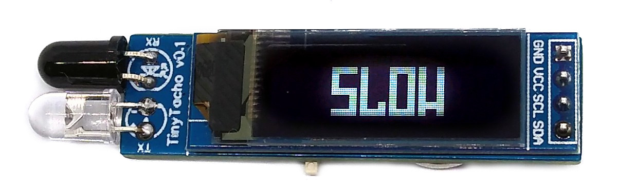
TinyTacho - Simple RPM-Meter based on ATtiny13A
Recently Great Scott built his DIY version of a tachometer which I thought was very cool. But using an ATmega for this job, I found a bit overpowered. So I tried to force all tasks (measurement, calculation, I²C protocol and OLED display) into the huge 1KByte memory of an ATtiny13A.
- Project Video (YouTube): https://youtu.be/Iz7LjheLYKo
- Design Files (EasyEDA): https://easyeda.com/wagiminator/attiny13-tinytacho
Hardware
Since the ATtiny13 does almost all of the tasks, the wiring is pretty simple:
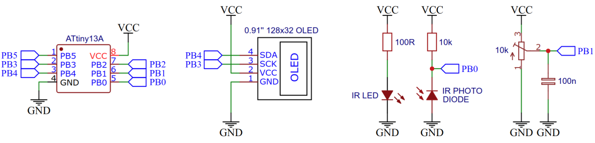
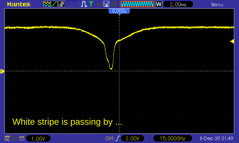
The IR LED emits light, which is reflected by the rotating object and detected by the IR photo diode. The photo diode changes its conductivity depending on the strength of the reflected light. If the rotating object has exactly one white stripe on an otherwise black surface, then the photo diode changes its electrical resistance twice per revolution and the voltage between the diode and the 10k resistor rises once above and falls once below a certain threshold, which is defined by the variable resistor.
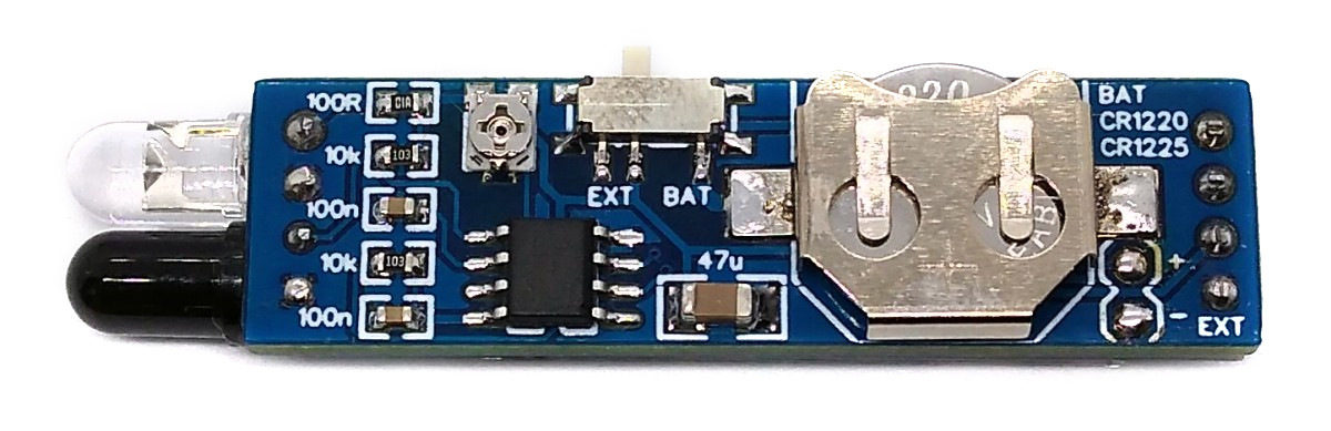
If you want to use a coin cell to power the device, please remember that only the rechargeable LIR1220 Li-Ion batteries work. The "normal" CR1220s don't deliver enough power.
Software
Implementation
The IR photo diode is connected to the positive input of ATtiny's internal analog comparator, the variable resistor for calibration is connected to the negative input. An interrupt is triggered on every falling edge of the comparator output which saves the current value of timer0 and restarts the timer. The 8-bit timer is expanded to a 16-bit one by using the timer overflow interrupt. The saved timer value contains the timer counts per revolution. The RPM is calculated by utilizing the following equation:
RPM = 60 * F_CPU / prescaler / counter
    = 60 * 1200000 / 64 / counter
    = 1125000 / counter
The calculated RPM value is displayed on an I²C OLED display. The I²C protocol implementation is based on a crude bitbanging method. It was specifically designed for the limited resources of ATtiny10 and ATtiny13, but should work with some other AVRs as well. The functions for the OLED are adapted to the SSD1306 128x32 OLED module, but they can easily be modified to be used for other modules. In order to save resources, only the basic functionalities which are needed for this application are implemented. For a detailed information on the working principle of the I²C OLED implementation visit TinyOLEDdemo.
// global variables
volatile uint8_t counter_enable = 1; // enable update of counter result
volatile uint8_t counter_highbyte = 0; // high byte of 16-bit counter
volatile uint16_t counter_result = 0; // counter result (timer counts per revolution)
// main function
int main(void) {
uint16_t counter_value; // timer counts per revolution
uint16_t rpm; // revolutions per minute
PRR = (1<<PRADC); // shut down ADC to save power
DIDR0 = (1<<AIN1D) | (1<<AIN0D); // disable digital input buffer on AC pins
ACSR = (1<<ACIE) | (1<<ACIS1); // enable analog comparator interrupt on falling edge
TIMSK0 = (1<<TOIE0); // enable timer overflow interrupt
sei(); // enable all interrupts
OLED_init(); // initialize the OLED
// main loop
while(1) { // loop until forever
counter_enable = 0; // lock counter result
counter_value = counter_result; // get counter result
counter_enable = 1; // unlock counter result
if (counter_value > 17) { // if counter value is valid:
rpm = (uint32_t)1125000 / counter_value; // calculate RPM value
OLED_printW(rpm); // print RPM value on the OLED
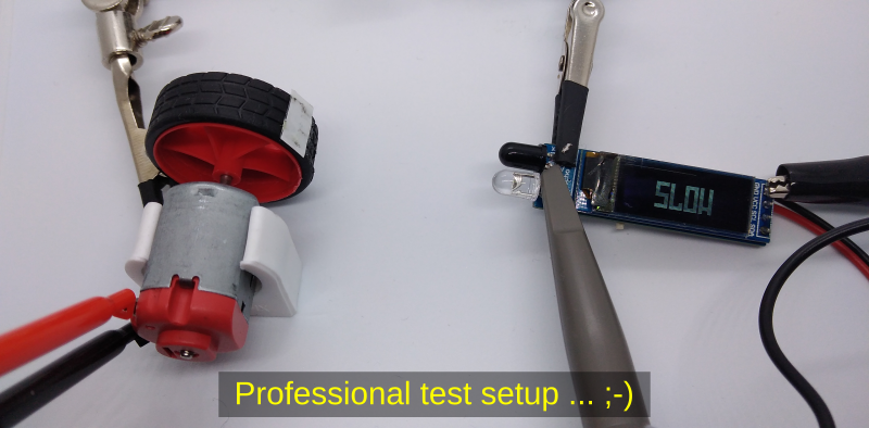
} else OLED_printB(slow); // else print "SLOW" on the OLED
}
}
// analog comparator interrupt service routine
ISR(ANA_COMP_vect) {
if(counter_enable) counter_result = (uint16_t)(counter_highbyte << 8) | TCNT0; // save result if enabled
TCNT0 = 0; // reset counter
counter_highbyte = 0; // reset highbyte
TCCR0B = (1<<CS01) | (1<<CS00); // start timer with prescaler 64 (in case it was stopped)
}
// timer overflow interrupt service routine
ISR(TIM0_OVF_vect) {
counter_highbyte++; // increase highbyte (virtual 16-bit counter)
if(!counter_highbyte) { // if 16-bit counter overflows
TCCR0B = 0; // stop the timer
if(counter_enable) counter_result = 0;// result is invalid
}
}Compiling and Uploading
Since there is no ICSP header on the board, you have to program the ATtiny either before soldering using an SOP adapter, or after soldering using an EEPROM clip. The AVR Programmer Adapter can help with this.
If using the Arduino IDE
- Make sure you have installed MicroCore.
- Go to Tools -> Board -> MicroCore and select ATtiny13.
- Go to Tools and choose the following board options:
- Clock: 1.2 MHz internal osc.
- BOD: BOD disabled
- Timing: Micros disabled
- Connect your programmer to your PC and to the ATtiny.
- Go to Tools -> Programmer and select your ISP programmer (e.g. USBasp).
- Go to Tools -> Burn Bootloader to burn the fuses.
- Open TinyTacho.ino and click Upload.
If using the precompiled hex-file
- Make sure you have installed avrdude.
- Connect your programmer to your PC and to the ATtiny.
- Open a terminal.
- Navigate to the folder with the hex-file.
- Execute the following command (if necessary replace "usbasp" with the programmer you use):
avrdude -c usbasp -p t13 -U lfuse:w:0x2a:m -U hfuse:w:0xff:m -U flash:w:tinytacho.hex
If using the makefile (Linux/Mac)
- Make sure you have installed avr-gcc toolchain and avrdude.
- Connect your programmer to your PC and to the ATtiny.
- Open the makefile and change the programmer if you are not using usbasp.
- Open a terminal.
- Navigate to the folder with the makefile and sketch.
- Run "make install" to compile, burn the fuses and upload the firmware.
Performance
Theoretical Considerations
Measuring Range
The measuring range depends on:
- the width of the timer/counter (here 16 bit)
- the width of the result variable (here 16 bit)
- the clock frequency of the timer/counter (CPU clock / prescaler, here: 1.2MHz / 64 = 18.75 kHz)
This results in a measuring range from 17 to 62500 RPM. To increase the measuring range, on the one hand the clock frequency of the timer must be increased by decreasing the prescaler and/or increasing the CPU clock frequency, on the other hand the counter and result variables must be expanded to 32 bits. Furthermore, the OLED_printW routine must be adapted so that 32 bit values can be displayed on the OLED.
Measuring Resolution
The measuring resolution depends on the resolution of the timer/counter, which is in fact its clock frequency. Due to the calculation formula, the RPM value is not proportional to the value of the counter, it is rather hyperbolic. This also means that the measurement resolution is not constant over the entire measurement range. With the set clock frequency of the timer/counter of 18.75 kHz, the following resolution results depending on the measured RPM:
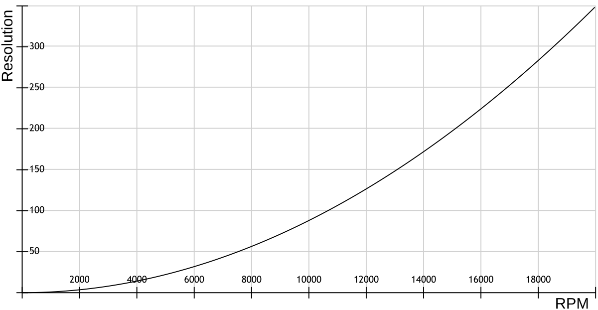
The resolution in the diagram shown means the minimum distance between two measured values (the higher the value, the worse the resolution). To improve the resolution, the clock frequency of the timer/counter must be increased (see above). In order not to reduce the measuring range as a result, the counter and result variables must be extended to 32 bits.
Measuring Accuracy
The measurement accuracy essentially depends on the accuracy of ATtiny's internal RC oscillator. According to the data sheet, this is +/-10% with the factory calibration. This can be improved to +/-2% by manual calibration. For even better values, a precise external clock signal would have to be used, but this exceeds the purpose of this project. With high RPM values, the latency of the interrupt service routine must also be considered.
Practical Review
Plausibility Check
A simple plausibility check can be carried out with the video method at lower speeds. More details can be found in Great Scott's video. In addition, the measured values can be compared with the manufacturer's specifications for the motor on which the RPM was measured. The TinyTacho passed both tests.
Oscilloscope
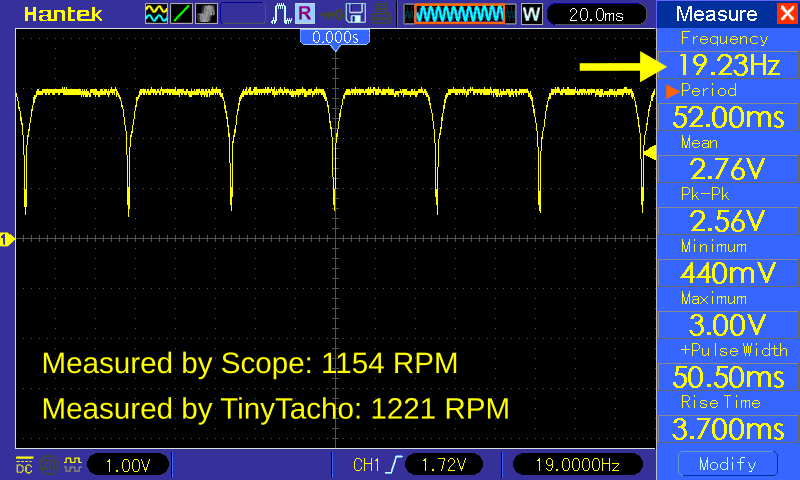
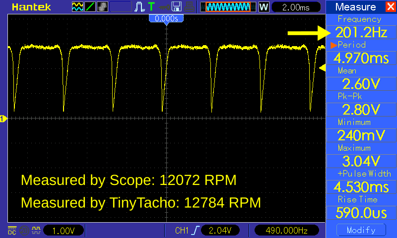
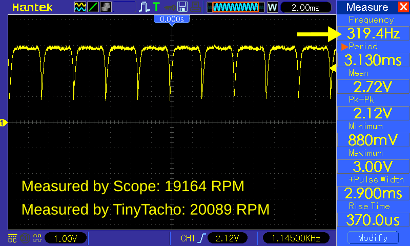
The voltage behavior at the cathode of the photodiode can be measured with an oscilloscope. First of all, it can be assessed here whether there is a uniform, clean and glitch-free wave, and thus whether a reasonable detection of the white stripe passing by is possible at all. The frequency of the wave measured on the oscilloscope then automatically indicates the number of revolutions per second. If you multiply this value by 60 you get the RPM and can compare this with the value displayed on the OLED. In all measurements, this value was within the theoretically predicted accuracy (the oscillator of the ATtiny was not manually calibrated).
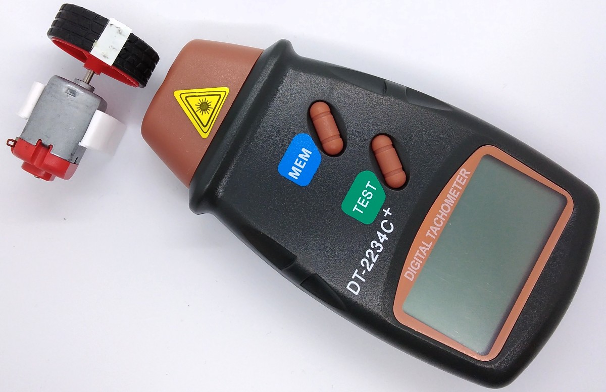
Comparison with Commercial Device
The comparison with the measured values of the cheap commercial tachometer DT-2234C+ showed the same results as with the oscilloscope.
Bottom Line
Even if TinyTacho was intended more as an educational and fun project, it delivers plausible readings, especially with a calibrated oscillator. In contrast to the commercial products, it is much smaller and significantly cheaper. If you can do without very accurate measured values with high resolution, then the TinyTacho is a useful measuring instrument.
References, Links and Notes
- Great Scott's Tachometer
- ATtiny13 I²C OLED Tutorial
- SSD1306 Datasheet
- ATtiny13A Datasheet
- Calibrating ATtiny's Internal Oscillator
License

This work is licensed under Creative Commons Attribution-ShareAlike 3.0 Unported License. (http://creativecommons.org/licenses/by-sa/3.0/)