Gowla-Macro-Boards
- Gowla Macro Board V1
✔️ - 9 Key Macro board for MX style switches.
- Gowla-Macro-eRGB
✔️ - 9 Key Macro Board with easy underglow RGB and Rotary Encoder support.
- MEK-Light | Tapedeck - Soon to be available March 2023
❌ - 12 Key editing keyboard with 60mm fader or 30mm + oled, two rotary encoders and underglow lighting.
- Gowla Keyboard-1
❌ - 44 key Ortho Keyboard built around the Pi Pico with Encoders, Sliders and Glow. In the works.
For fully built macro keyboards with cases, follow my eBay store as these will only be listed when I have parts available.


Gowla-Macro-Board-V1
Version 1 PCB is where this project all started and is available to buy, it's fully supported in QMK and super simple to put together! Great for practicing your soldering skills and getting started into mechanical keyboards.

Purchase
To purchase a PCB for DIY assembly and to support this project please visit my eBay Page.
For additional options such as plates, hardware, RGB and more visit the new! multi variation page : Variations eBay Page
Required Parts
-
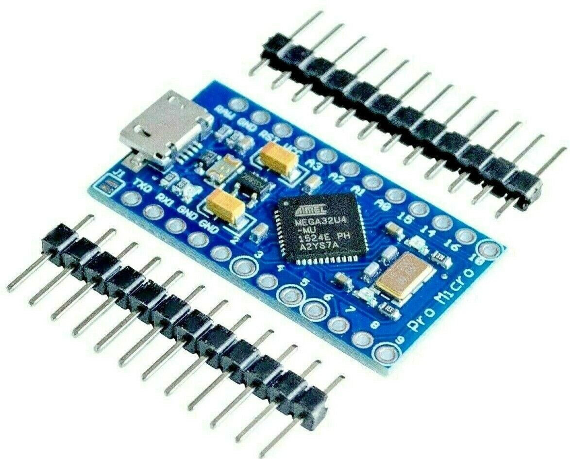
1 x Pro Micro ATMEGA32U4 5V 16MHz (Micro USB) - Sparkfun/Clone Size
-
9 x 1N4148 Diodes.
-
9 x PCB or Plate Mount Switches (Cherry MX or Clones).
-
9 x Key Caps.
-
8 x *M2, 6mm (min) to 10mm (max) body length + 3mm thread Stand Off Spacers Male-to-Female
Please note there's a variety of different hardware options. At a minimum you will need your PCB 6mm off the ground, though for the best compatibility I would recommend 8mm.
Assembly
Asssembly will require the use of a soldering iron, solder and some tape is recommended for holding components. The order of assembly is important for the complete 9 switches.
-
Start by folding the legs of your diodes, with approx 3mm of space either side of the diode in wire.
-
Pull all diodes through the pcb holes, making sure the direction of the diode matches the image printed on the PCB. With the black mark in the direction towards the line.
-
Solder your diode legs and then cut the excess, leaving a little length for error.
-
Next solder in your top 3 switches.
-
Then solder in and/or socket your pro micro, you will at a minimum need the headers provided with most when ordered. Making sure the pro micro usb is pointing outwards away from PCB and on the underside of the PCB.

-
Once the Pro Micro is in, continue to solder your remaining switches.
-
Finish by adding key caps and screws, then move onto programming or flashing the firmware.

Simple Programming
You can build and compile new keyboard layouts most simply by using the web configurator : https://config.qmk.fm/#/gowla/LAYOUT_ortho_3x3
For more advanced programming follow the QMK tutorials.
The default build is also available for use through QMK toolbox and files available within the QMK Firmware repository.
Prebaked Firmware Profiles
Images for each of the profiles can be found in the images directory.
If you wish to add your template for other users to use, please create an issue, prefixing the issue name with "Profile".
Flashing a Pro Micro
To flash a pro micro with your newly built or prebaked firmware you must get it into DFU mode, short the reset and ground pins. Shorting once will put into DFU for 750ms, you can use QMK toolbox to dectect DFU and automatically flash once detected.
Double resets, to keep the pro micro in DFU mode for longer short reset and ground twice quickly. This will keep it in DFU mode upto 8 seconds allowing you to manually flash the pro micro with QMK toolbox or AVRdudess GUI.
You can use either of the following software to flash your pro micro.
Top Plates
To further improve aesthetics an additional top plate is available to buy, top plates only come in gloss white from now on. Matte blacks were experimented with but scratch too easily. These are available to buy now at the new multi variation ebay listing, along with new white PCBs: eBay Page
Top plates require additional hardware, M2 hardware is inculuded when purchasing a Top Plate. 3mm spacers between the plate and the PCB. 8mm spacers and 8mm M2 machine screws.

Case in the works
Currently I am working towards a low cost case design and intend it to look like the render below. The case will work with any updated PCB designs. So far I have designed and 3D printed these. But to improve surface finish and reduce print time the top plates will be laser cut. Top plates will be available in either black and white.
STL files are provided for the case design within this repository. However you will need some additonal M2 hardware and no assembly instructions are currently provided.

Gowla-Macro-eRGB
Designed to make RGB lighting as easy as possible and add support for an optional rotary encoder (Alps EC11)
On sale now through the Variations eBay Page
eRGB is backwards compatible with V1 firmware, you maybe recieve an eRGB board if you order pcb only . These can be assembled as V1s or with the additional features.


Some Assembly Tips (In order):
When building take your time, and keep in mind not to block anything off before soldering it :)
- Start by soldering all your diodes into place.
- Solder the pin headers for your pro micro but not the pro micro it's self yet.
- Connect the plate to the PCB with 3mm spacers using the 8mm M2 scerws between the PCB and Top Plate or push switches through plate first. Head of machine screw will be on top the top plate, going through both the spacer and PCB into the 8mm bottom spacer. You may need to trim the height of the headers on the top side so they don't block the top plate. You could place switches into top plate first either.
- Push your switches into plate and through the PCB, soldering down all your switches or 8 if your doing bottom left as rotary encoder.
- Solder the Pro micro to the pin headers.
- Solder RGB LEDs and rotary encoder if applicable.
eRGB Firmware
The firmware process for eRGB is a bit more involved at the moment, until it's no longer early access.
Example firmware is provided within eRGB Folder.
Please note, the following lines differ in config.c for black and white PCBs, black eRGB are an older revision.
For white PCBs encoder and RGB pins should match this, surrounding code is not shown just update the 3 lines.
/* RGB */
#define RGB_DI_PIN B6

...

/* Rotary Encoder*/
#define ENCODERS_PAD_A { B2 }
#define ENCODERS_PAD_B { B3 }
MEK-Light-RGB
coming very soon.
Kit Options
- Build Kit 1:
- Link:
- Included Parts: PCB, Top Plate, Alps 60mm Dual Linear Pot, 3 x RGB LEDs, Diodes, 330R Resistor, M2 Assembly Hardware
- Required Parts: Pro Micro 5V, 2 x Alps EC11, MX Switches, Keycaps
- Build Kit 2:
- Link:
- Included Parts: Kit 1, Bottom Case, 2 x Alps EC11
- Required Parts: Pro Micro 5V, MX Switches, Keycaps
Build Guide
Straight forward but will require the use of a soldering iron, solder, wire cutters, time and maybe some tape for holding components. Before starting check you have all the required parts.
Note: Order of Assembly matters, don't start with switches.

-
Start by folding the legs of your 14 diodes, with approx 3mm of space either side of the diode in wire.
-
Pull all diodes through the PCB holes, making sure the direction of the diode matches the image printed on the PCB. Note the direction of diodes is different for the two encoders.
-
Solder your diode legs and cut the excess.
-
Solder the 330 Ohm resistor marked on the backside.
-
Then solder in and/or socket your pro micro, you will at a minimum need the headers provided with most when ordered. Making sure the pro micro usb is pointing outwards away from PCB and on the underside of the PCB.
-
Solder the Encoders to the PCB.
-
Solder the 60MM fader to the PCB.
-
Grab your top plate, place the long M2 machine head screws through the plate and thread the 2mm spacer up to the top plate just like this image.
-
Attach your top plate to the PCB by threading the gold standoffs on the machine head screws going through both the top plate and PCB.

-
Push down your switches into the top plate, soldering the pins connected to the PCB.
-
Place your 3 x adhesive RGBs between the marked positions on the backside of the PCB, ensuring they match the correct direction (DI to DO) and solder between the pad and bridge. As shown here below.

- Dress up with Keycaps and Knobs. Then Flash an example or custom firmware and play with your board!
Usage and EULA
Design and profiles are made freely available for personal usage only and no further commercial usage. By downloading or using files within this repository users agree to not resell or redistribute the designs or files.
Additional Use Cases
Find additional use cases for the PCB within the Uses directory, a nice example is dan-r's IR Remote use case.
Maintainers
Getting Help
Please report issues you encounter to the Gowla-Macro-Board Issue Tracker, prefixing the issue name with "Macro".