
A discrete transistor implemenation of a Kansas City Standard data tape decoder and viewer. This is my entry for the RetroChallenge RC2018/09.
The entries/blog here will be kept in chronological order with the newest post at the bottom.

Sep 01 - Intro
For this challenge I'll attempt to make a decoder/viewer for the old Kansas City Standard tapes that once was the standard for storing data and programs on regular cassette tapes.
Since I have a thing for using discrete transistors instead of ICs I'll make it with just Q's R's and C's. Maybe a D and some LEDs will appear as well, but definitely no ICs.
The KCS is a simple low speed (300 bps) FSK (Frequency Shift Keying) that are using 1200 and 2400 Hz to represent the zeros and ones in the data stream. A zero is four cycles of 1200Hz, and a one is eight cycles of 2400Hz.
Every byte are, just as in a regular asynchronous UART, prepended with a startbit that is a zero, followed by the eight databits, and then finally one or two stopbits that are high.
The next byte can then start directly after that (with its own startbit of course) or after an arbitrary number of high bits.
This fully asynchronous signalling makes it rather easy to decode since there's no real need to make a PLL to recover the clock. Just as in an UART it's ok to just have a freerunning clock that is re-synchronized to the leading edge of each startbit. If the tape speed doesn't vary more than 5% the data should be decoded correctly.
Sep 01 - Plan of attack
The final goal is to be able to decode the FSK audio coming from a cassette tape or a sound file into a 8-bit parallel data with a data-valid strobe so it can be read by a computer to load software into it.
As an extended more fun goal would be to connect the outputs to a 7-segment display to display the data in real time. Considering the asynchronous nature of the KCS the audio stream could have just a single byte every second and fill the rest with just idle/mark data. Then a tape would display a message character by character on the display. Or to be a bit more fancy the eight databits could drive a standard HD44780 display in 4-bit mode to display a message on the 2x16 characters there.
Alternatively I could modify the standard a bit and have 14 databits instead of 8 and collect them all to be shown on a startbust display instead of the 7-segment. But that would require a higher degree of match between the freerunning clock and the actual speed of the tape.
So the high level overview of the design looks something like this
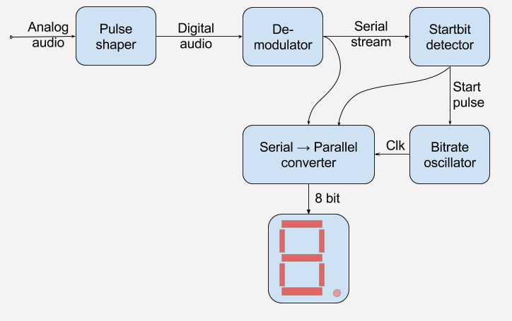
The pulse shaper will take the analog audio from the tape recorders line output, I guess something between 100 and 700mV, and shape it up into a nice digital square wave with logic (0/5 volt) levels.
This digital audio will still be modulated with the 1200/2400 Hz carrier so the next order of business will be to demodulate that so we get something that looks just like the output of a serial port.
The serial stream will enter both a shift register as well as a startbit detector.
The startbit detector will trigger (or resynchronize?) the oscillator that runs at 300 Hz, driving the SIPO (Serial In Parallel Out) shiftregister.
When all eight bits are shifted into the shiftregister it needs to be latched and a strobe pulse should be asserted. (This is not shown in the diagram above)
Sep 01 - Simulating the tape
I recently got hold of a working casette tape deck, but it will be a bit of a hassle to use that during development so I made an Arduino sketch that outputs any FSK bit sequence I need.
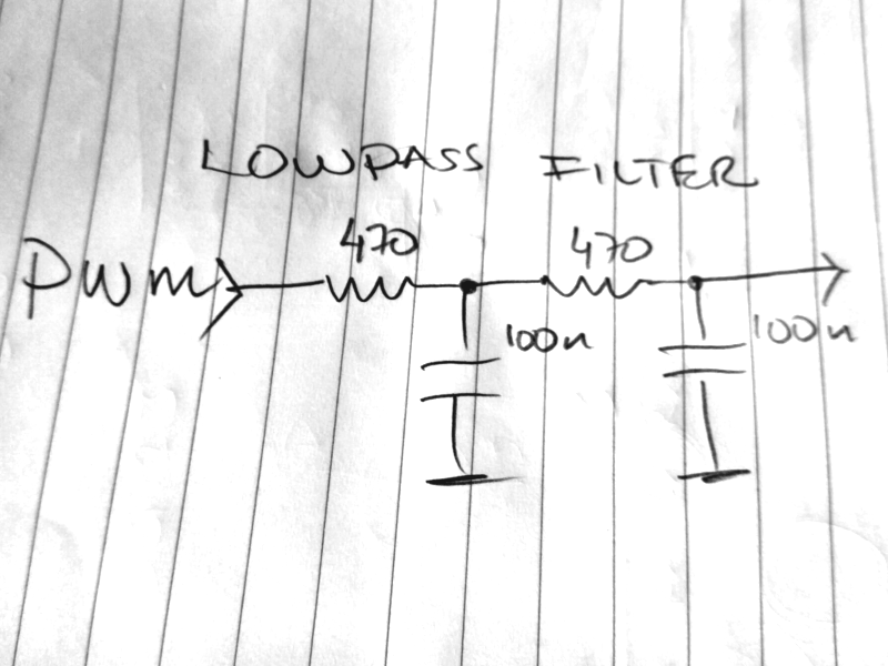
The Arduino doesn't have any analog out so it's emulated with a PWM followed by a simple lowpass filter to get rid of most of the PWM frequency.
I just soldered it up directly between a pinheader and a screw terminal. The pinheader connects to GND, D2 and D3 which conveniently are located next to each other on a Nano. D3 is used for the PWM and D2 is a reference output of the zeros and ones sent on the audio stream. This makes it easy to see what data bit that is actually being sent and how it passes through the circuit.

After writing some quick and dirty code (what else can be done using an Ardunio? ^__^ ) the output of a few bits looks like this

The code is available at GenerateKCS
As can be seen the lowpass filter isn't the best since the 2400 Hz of the ones are getting attenuated a bit more than I had wished for, but it's good enough for the time being. Maybe I'll make a steeper filter with a bit higher center frequency someday, we'll see....
Sep 02 - FSK→UART
Design & Schematics
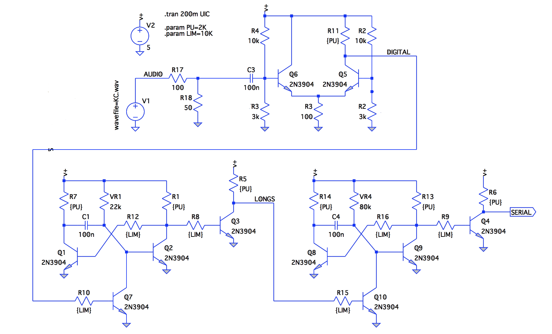
The first part of the process to convert the FSK-audio into a plain UART-like serial stream would be to shape it up into a nice square wave with full swing between GND and VCC.
I'm sure there's many ways of doing this, but I just made a long tailed differential amplifier with the second side fixed to the same bias voltage as is set on the fist side. This basically makes it into a comparator. Maybe some hysteresis would be a good thing to have as well, but I'll leave that out for the time being.
The now digital output (DIGITAL in the schematic) is used as a trigger for a monostable set at 300us. The 300us is longer than the 2400Hz pulse width so while 2400Hz is present the monoflop will continuously be re-triggered and will never time out. As soon as the input frequency changes to 1200Hz the timer will timeout and thus output a pulse before the next re-trigger some 10's of microseconds later.
At this point (LONGS in the schematic) there will be a pulse train whenever 1200Hz is present and a steady level whenever 2400Hz is present.
If this is fed into another monostable set at a even longer timeout (1100us) then the pulses in the pulse train will re-trigger the monostable and keep it active as long as the pulses are available.
The output from this last monostable is a plain and simple UART serial stream.
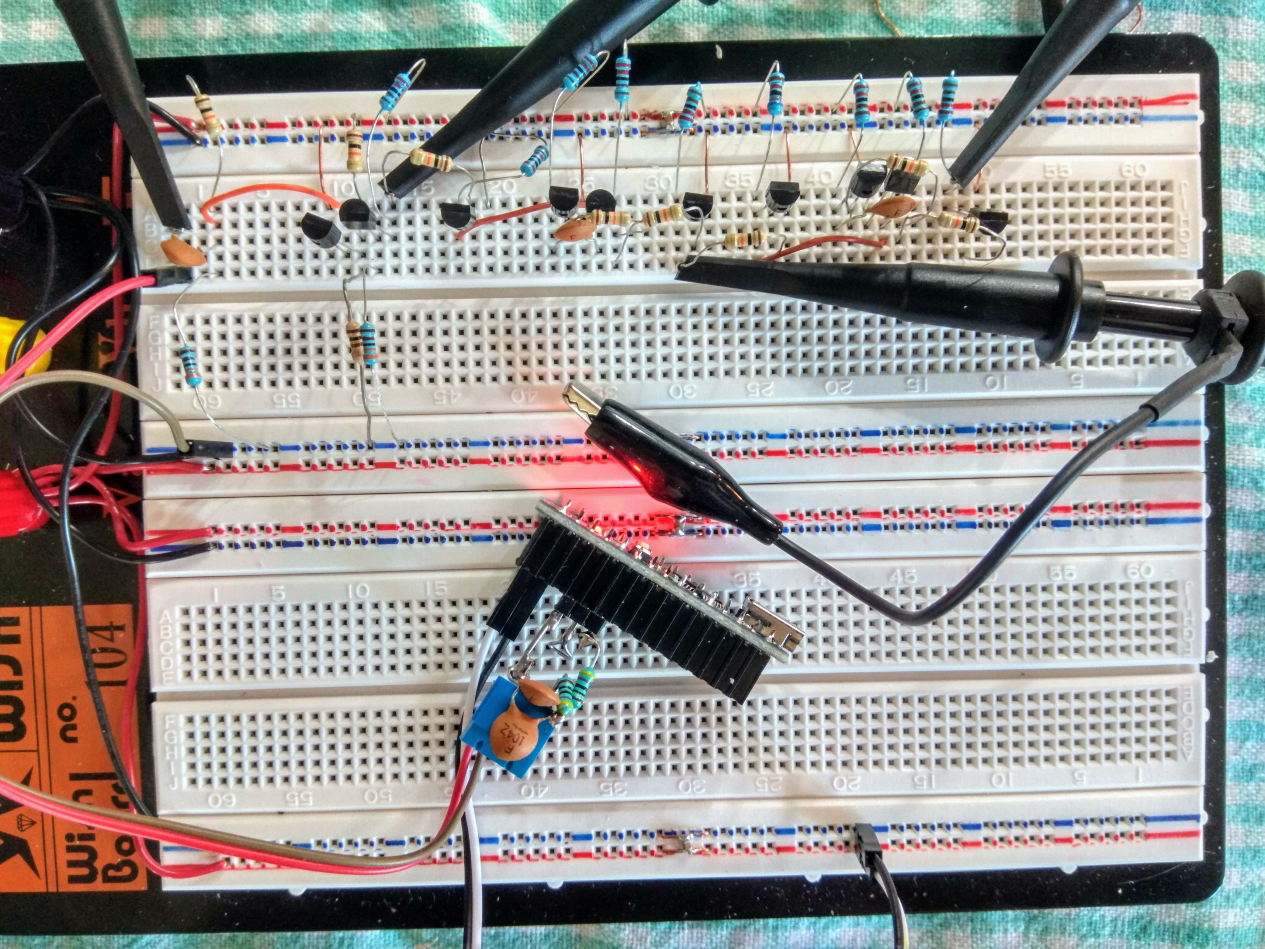
Prototype
I first built this on a solderless breadboard to verify my previous LTspice simulations. It worked like a charm!
PCB
Lately I've started to actually plan and design whenever I solder something on veroboard or donut-boards. For this I use DiyLC
So after a bit of trying out a few different layouts I came up with this design.
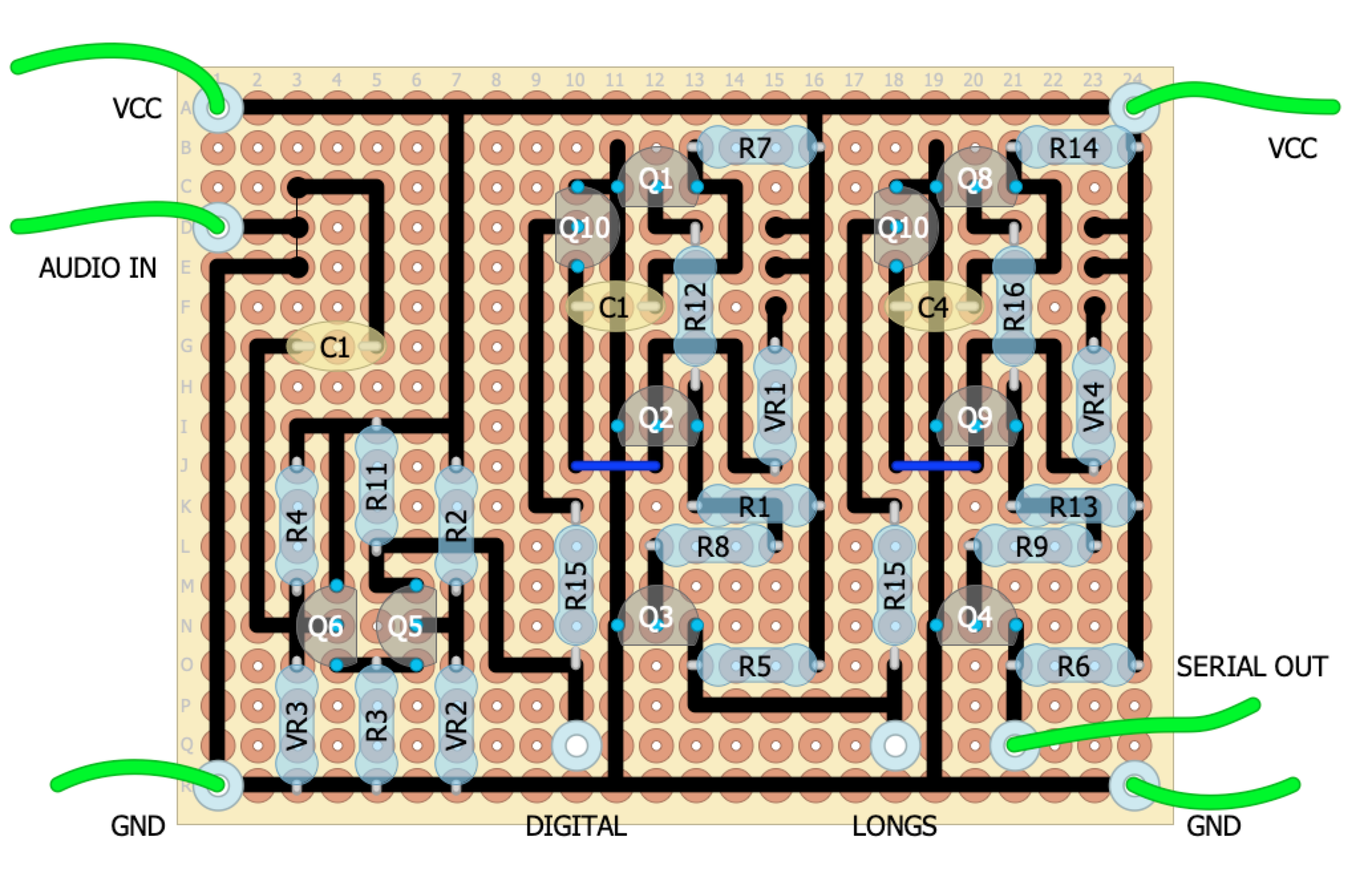
I find it easier to follow the layout during soldering if I first mark the tracks-to-be on the top with a pen like this:
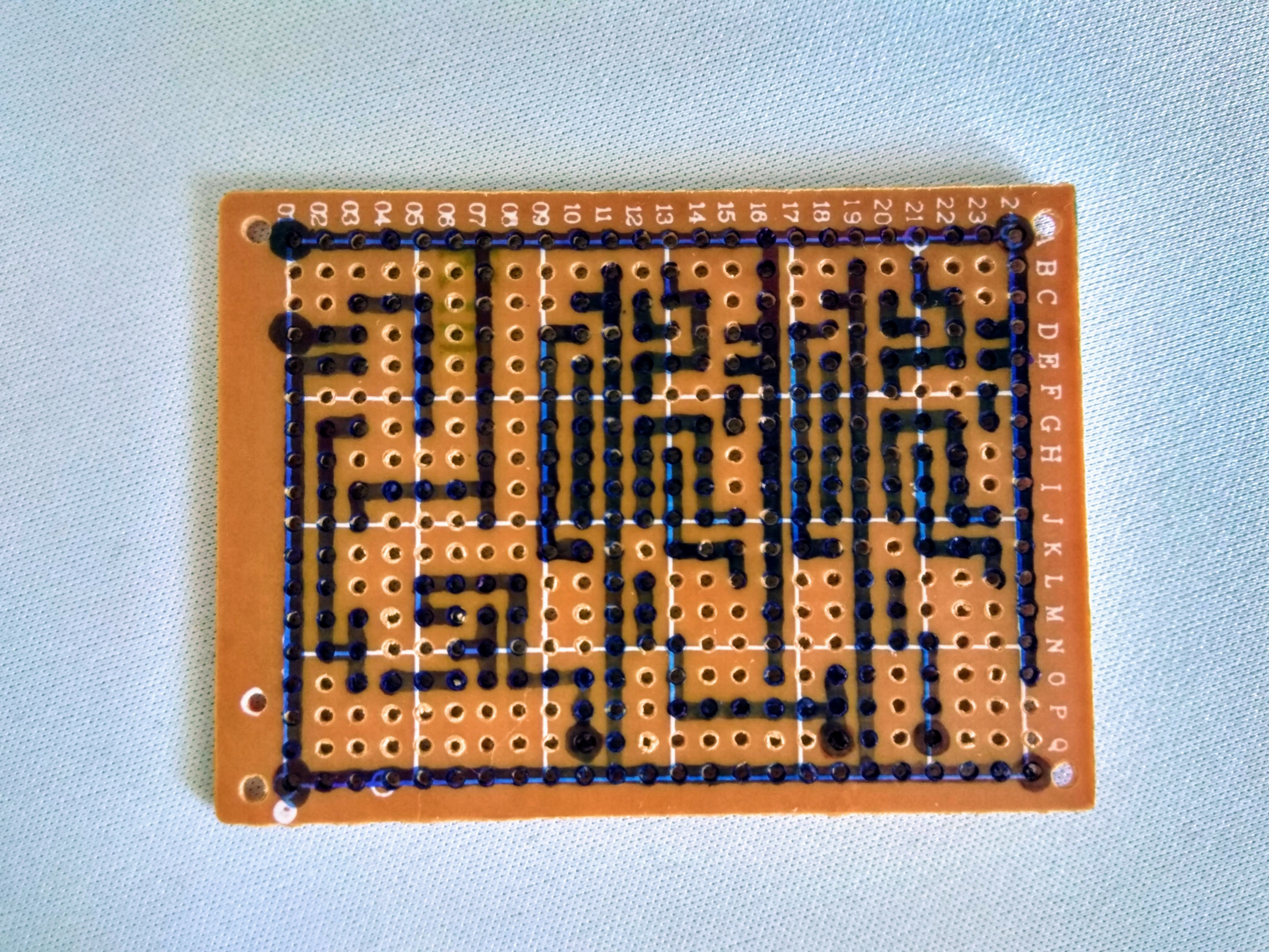
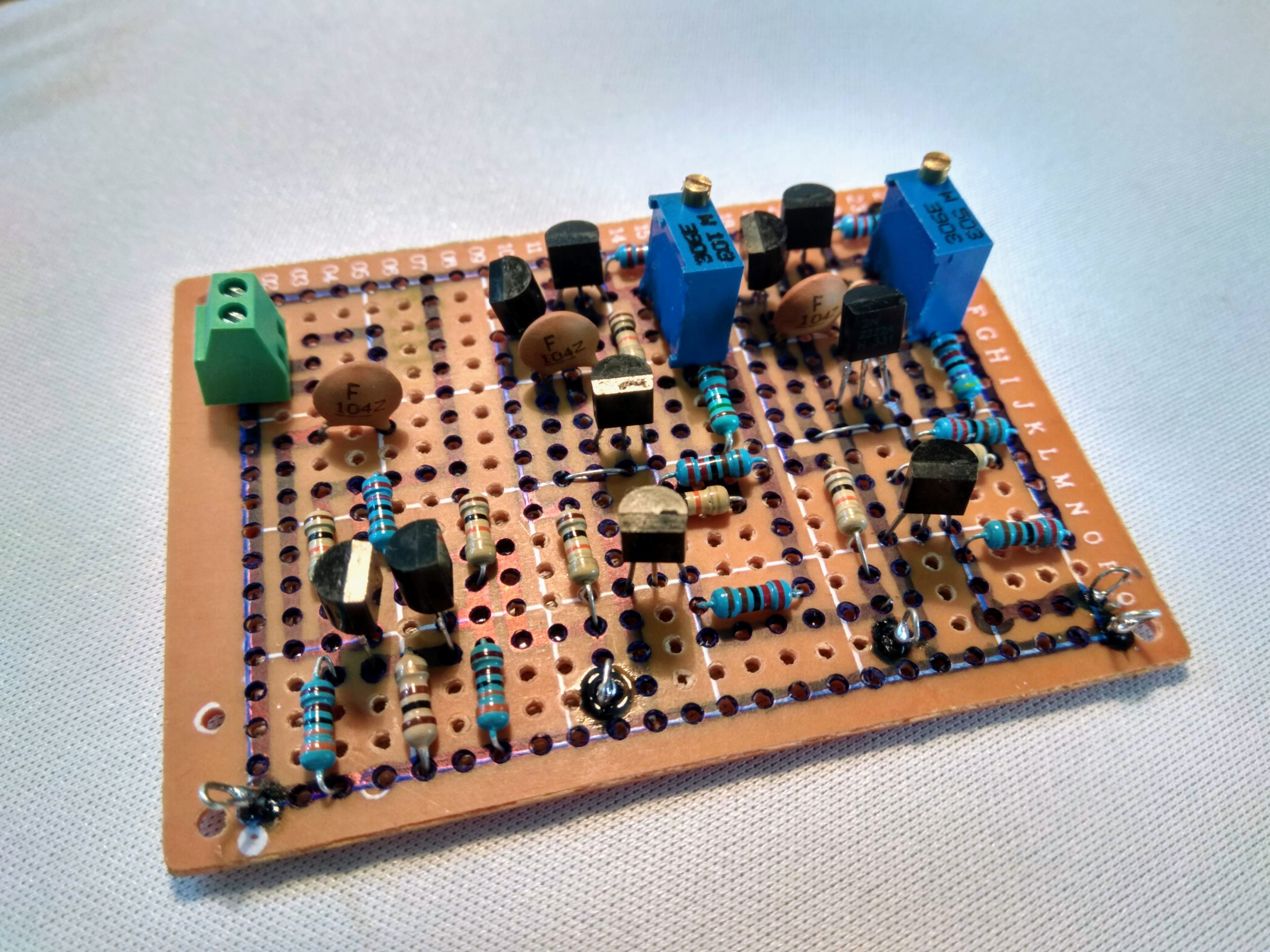
After this it's easy enough to just plonk down the parts, bend the component leads at the bottom in the right directions and solder&snip.
Testing
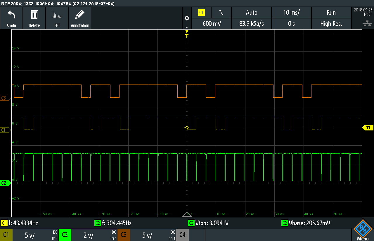
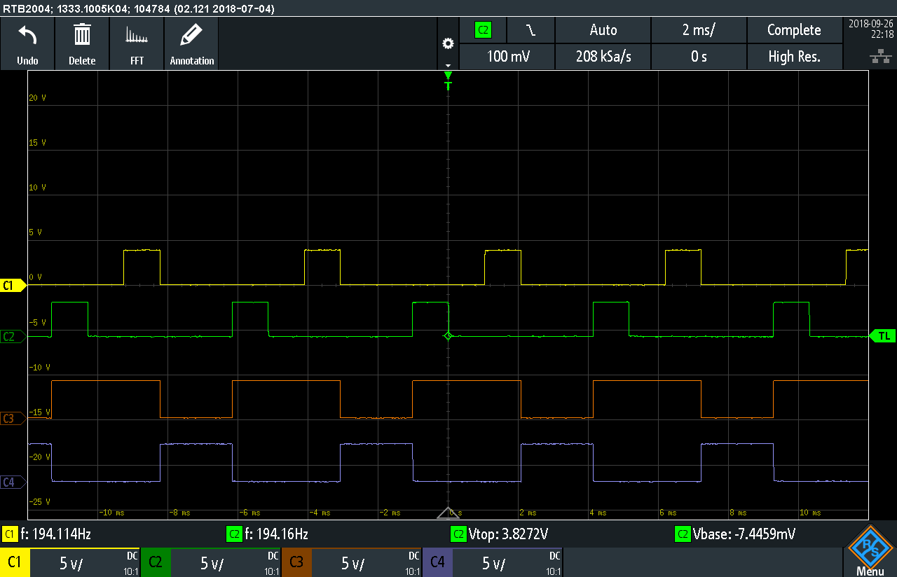
Feeding it a short FSK sequence from the Arduino KCS simulator I built/wrote yesterday it looks very good.
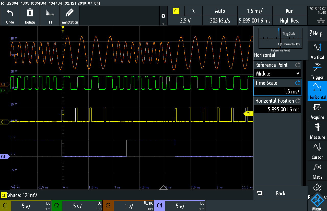
On the top in orange color we have the AUDIO input starting out at a (slightly attenuated) 2400 Hz followed by four cycles of 1200Hz, eight cycles 2400 and then some more 1200.
The next trace is the green DIGITAL output from the comparator.
The yellow trace is the LONGS pulse train from the output of the first 300us monostable.
And finally the blue trace which is the SERIAL output from the second 1100us monostable.
Sep 17 - Baud clock & Ring counter
No noes! Real life happened and made me work basically around the clock for two weeks, but now I got some breathing room to play with my #retrochallenge project for a bit again.
Done this time
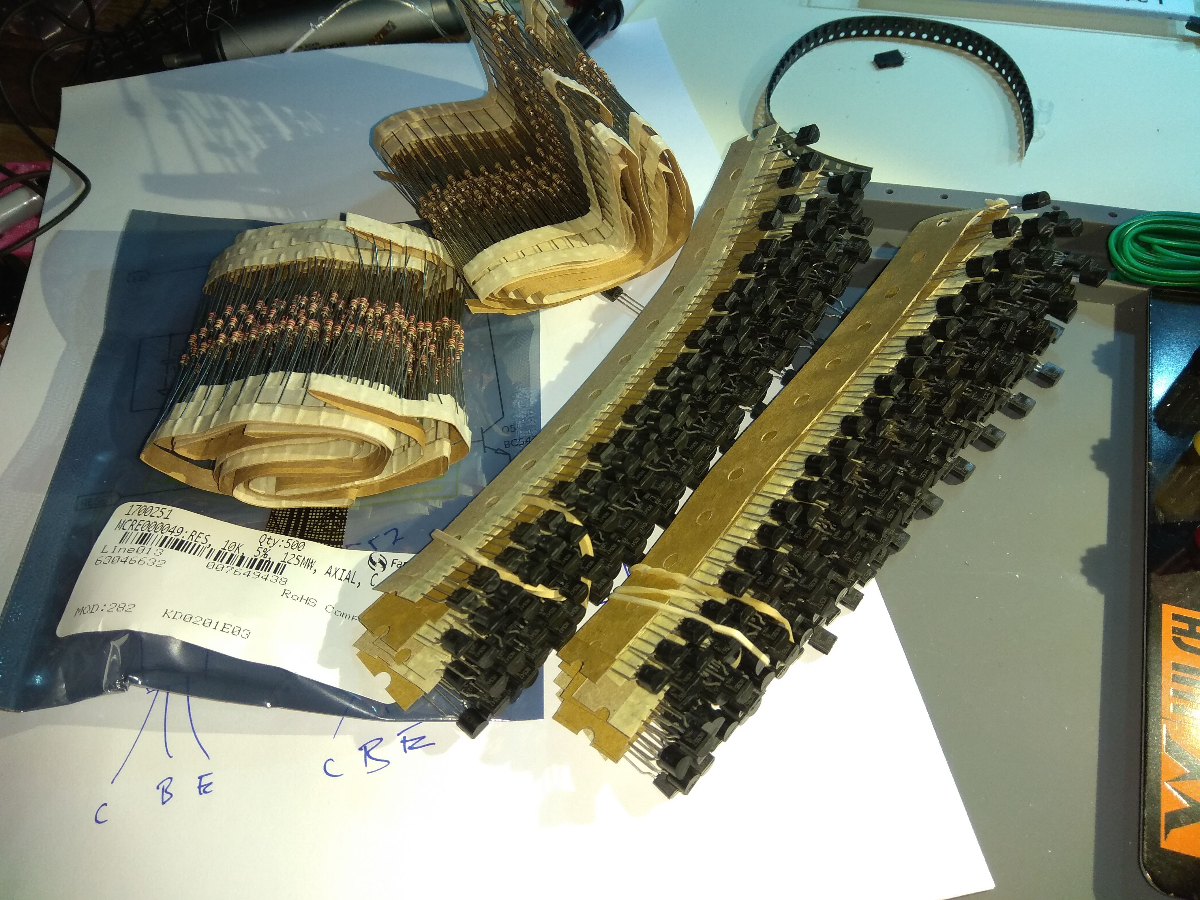
I was running out of 2.2k resistors and also started to get log on NPN's in TO-92 so I ordered 500 each of 2k2 and 10k plus a hundred each of NPN & PNP transistors. I hope they will not run out while doing this project..
My original plan was to do the startbit detection mono- and flipflops, but I realized that I needed the ring counter first in order to test that part of the design. So I went ahead with the clock generator, ring-bias and ring-stages this week.
Baudrate generator
In order to be able to collect the bits as they come in at 300 bits per second I need a 300Hz clock pulse that can be synched to the leading edge of the startbit. Without the syncing the sample point might end up anywhere in each bitslot and we want to sample as close to the middle as possible to have as much margin as possible if the playback tape speed is a tad slower or faster than the recording tape deck. Also the frequency of the clock generator here will vary a bit in response to the temperature.
A regular UART-chip usually have a clock that is 16 times the bit rate so it can digitally select the correct number of clock pulses to wait before reaching the mid-point, and they can also make multiple samples in each bit to ignore glitches. That is fine and dandy when you do it digitally and can use huge number of transistors inside the chip, but this project is more of less analog and have to be a bit frugal on the parts count so something else has to be done.
The idea is to have the clock generator stopped until a flipflop is "set" by the rising edge of the startbit in the serial bitstream. When the flipflop is set then the clock generator is started and will be free-running until all data bits are collected. At the stopbit the flipflop will be "reset" and the clock will be stopped.
The clock circuit looks like this:
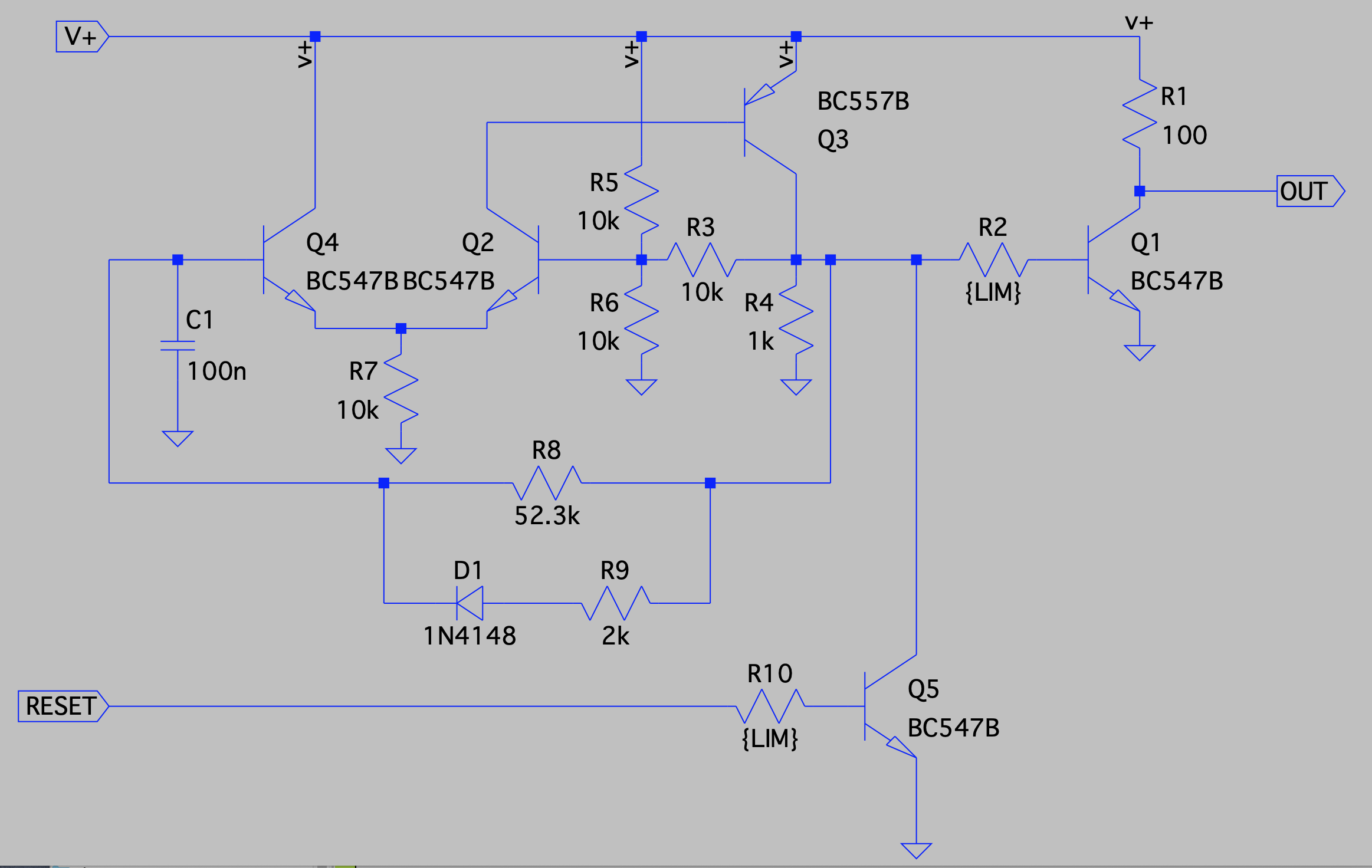
The C1 and the resistors R8 and R9 (together with D1 ) controls the frequency as well as the pulse width ratio. The diode makes sure that only the charging cycle of C1 will be affected by the low resistance of R9 (making it fast). The discharge will be done thru the much higher resistance of R8 making it slow.
This gives me pulses at 300 Hz with a very short low-going output that will be used to advance the ring counter one step.
The RESET/stop input of this module merely keeps the C1 capacitor in a permanent discharged state as long as it is asserted.
I just now discovered that there's a direct path between V+ and GND via Q3 and Q5 when the circuit is in the reset state - not good. The simulation says only 36 mA will flow though - that's only 180mW. But that is if one can trust the simulation to 100%.
I guess I have to come up with some better solution to the reset. I'd probably be better to hoo kQ5 directly up to C1 - I think my original thought was that I wanted to force the output transistor off directly with the reset, but that's probably not really necessary.
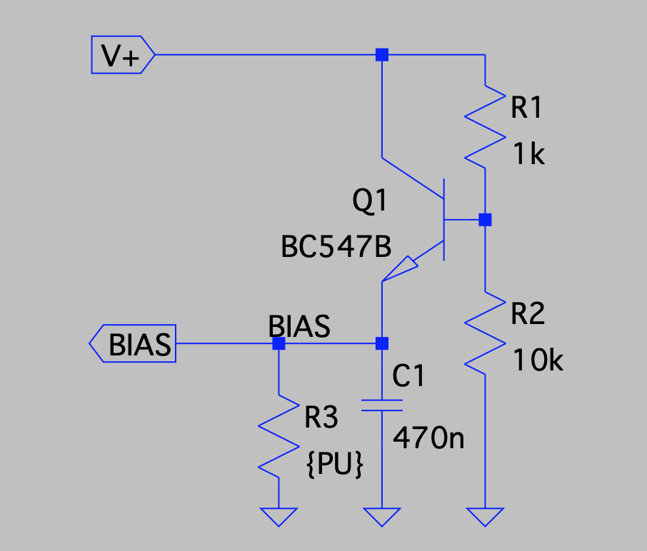
The bias generator
The chain of ring counter modules needs two things to operate. A the clock pulse (which is merely a short interruption of the VCC supply current into the modules), and a adjustable bias voltage.
The bias module is as simple as it gets - just a simple emitter follower controlled by a pot to adjust the voltage.
In the schematics (from the LTspice simulations) below I replaced the pot with the two R1 & R2 transistors.
Both the clockgen and the bias got fitted onto a single PCB without any issues.

Ending up in real life as this:

The picture was taken before I changed the R1/R2 voltage divider into a pot to be able to tweak the bias voltage.
Ring counter
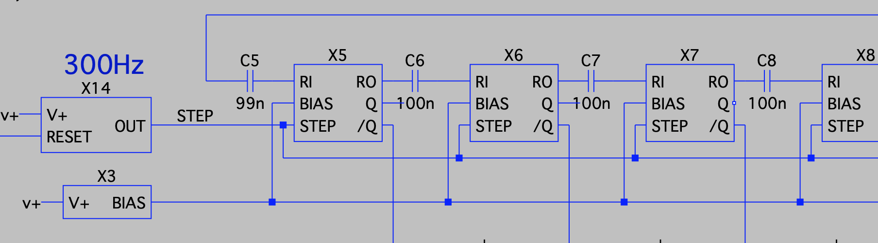
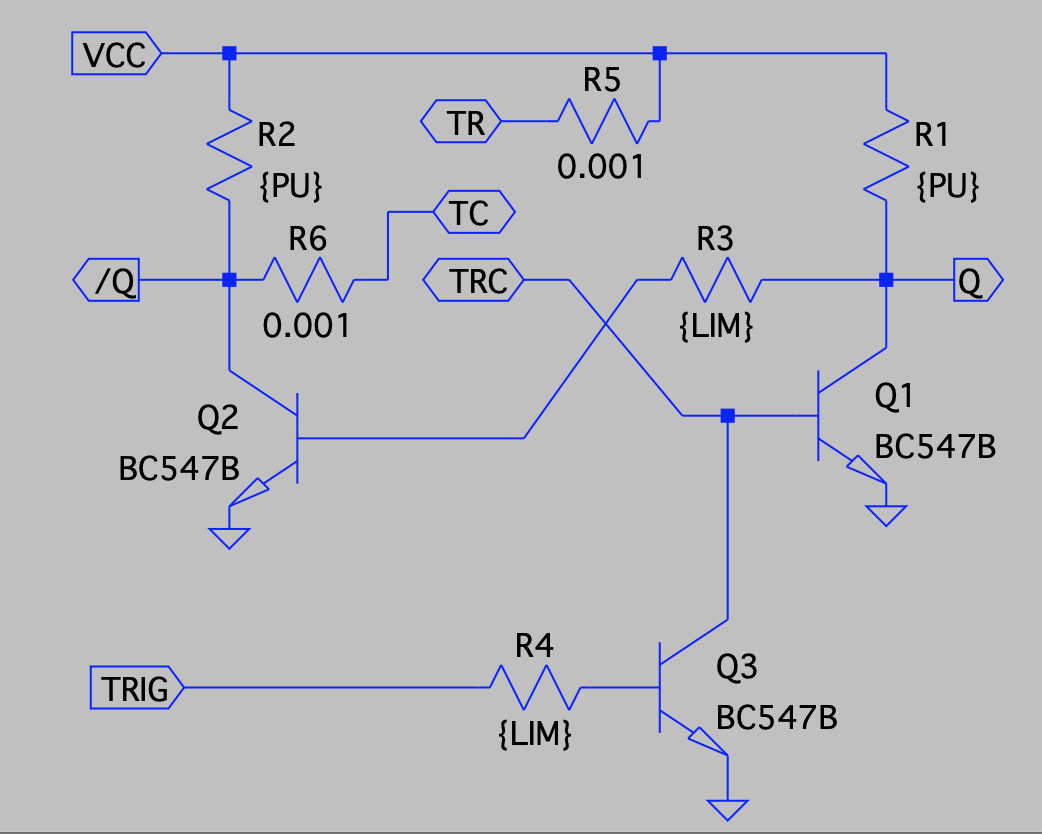
Each step of the ring counter is rather easy. They are being based on on a discrete BJT version of the usual thyristor-based ring counters.
The thyristors are build out of a tightly coupled NPN/PNP pair so they almost end up a 4-layer N/P device.
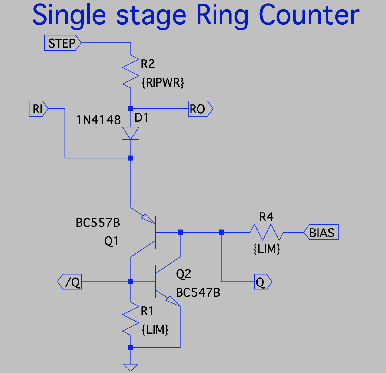
The RI and RO connects from/to the previous/next stage by a 100nF capacitor. The STEP is the power supply with brief interruptions coming from the baudrate/clock generator. Each dip in the power moves the active stage one step to the right. It works almost by magic ;-)
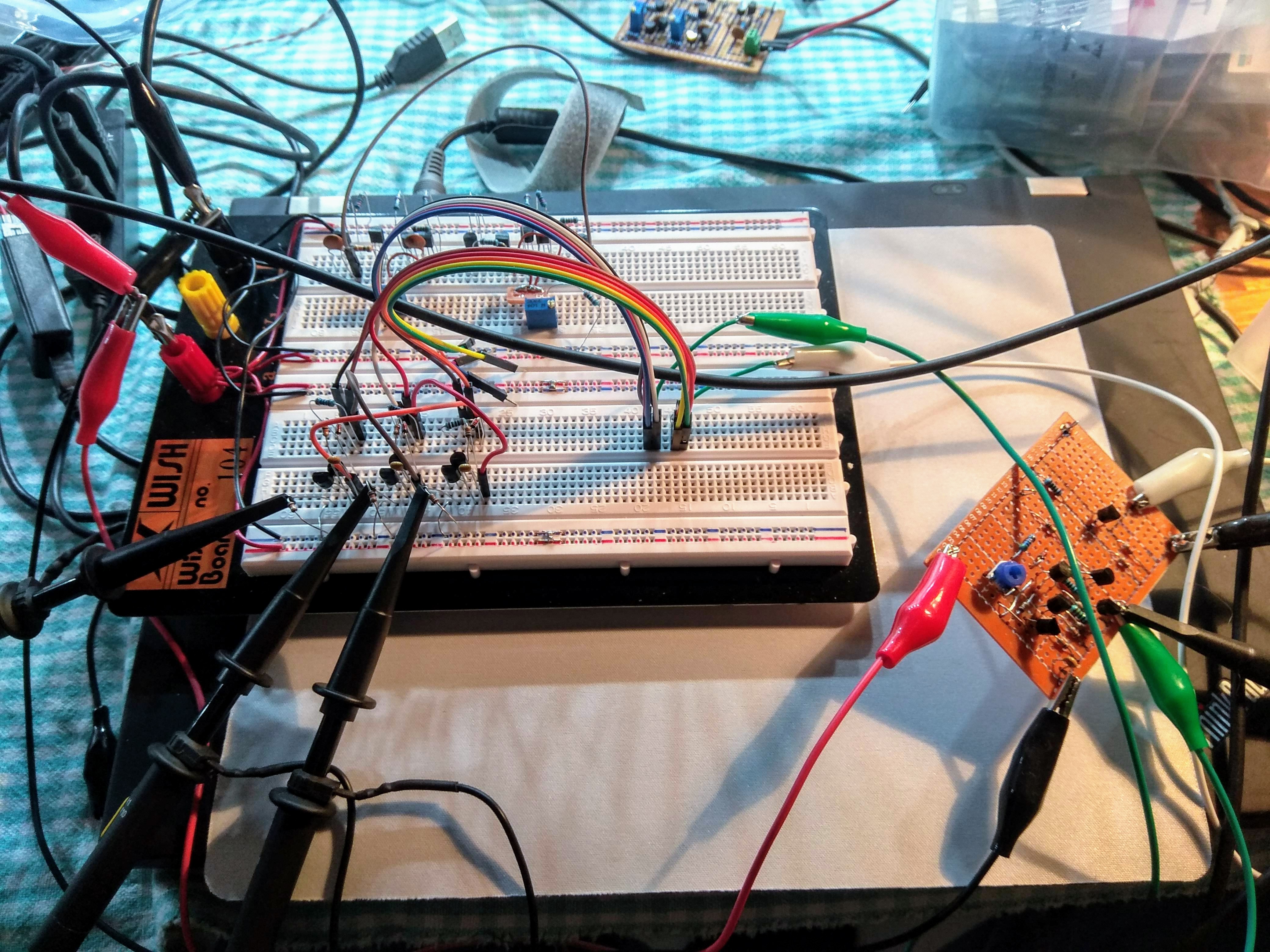
I hooked up three staked on the breadboard and connected the clock/bias PCB to it and the pulses shifted around beautifully just as planned.
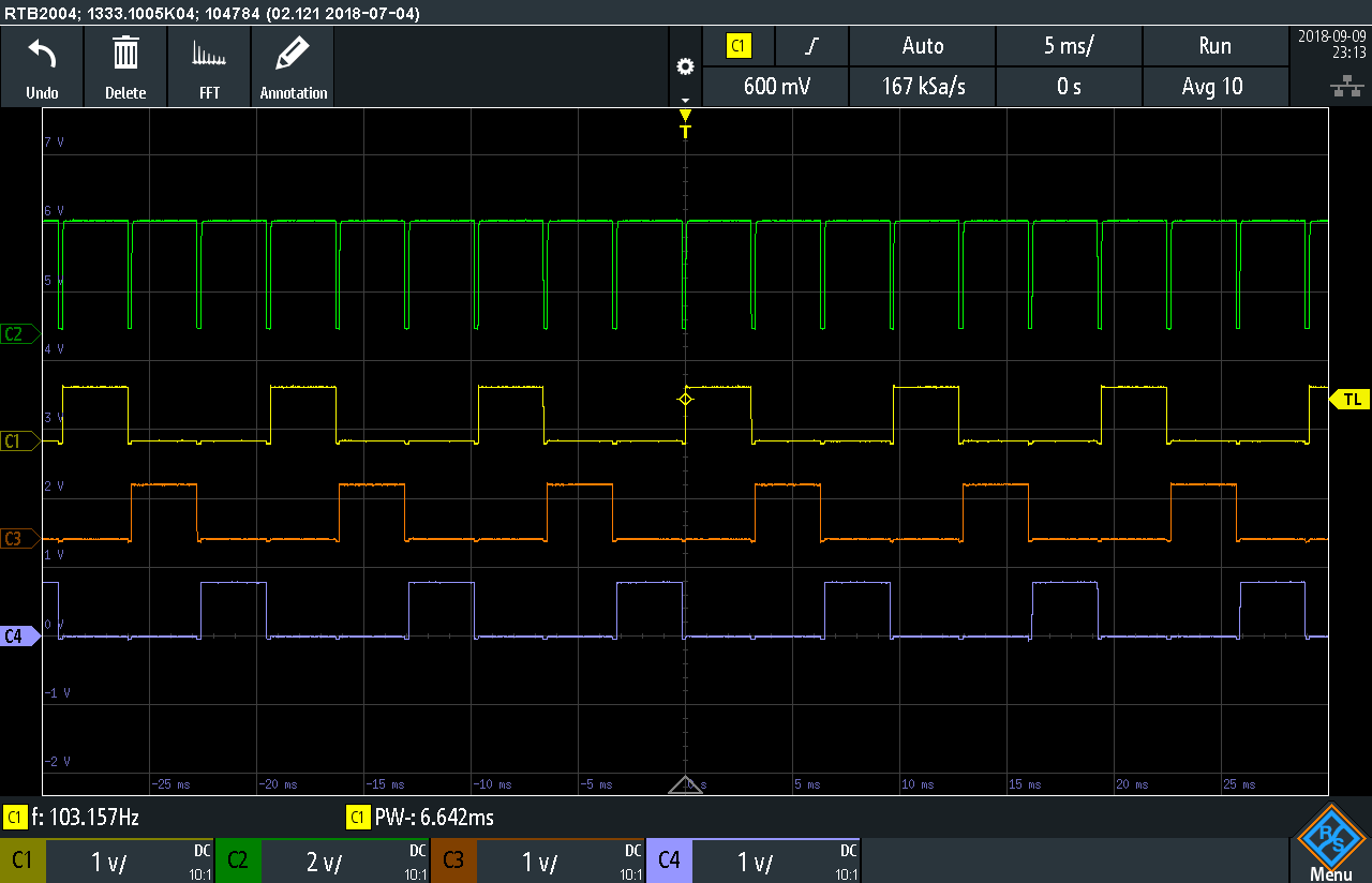
Screenshot from the oscilloscope showing the incoming STEP pulses and the outputs from each of the three stages.
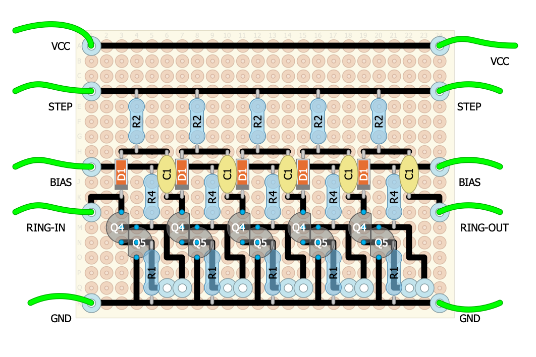
I did a quick layout with five stages on one of the usual PCBs - easy peasy.
By some reason the soldering took a while to do and I might have fscked up something because it didn't behave properly at 5 volts. I got a lot of double pulses at the outputs or all just toggled in tandem. Fiddling a bit with the bias voltage and raising the input voltage up to 12 made it better - but something is just simply wrong.

I didn't have time last weekend (when I snuck a few hours to solder all of this up) to debug the issue further. I didn't even have time to make this blogpost back then.
But tomorrow I'll spend some time to get to the bottom with this and also then solder up the second 5-stage ring counter.
Sep 22 - Debugging the ring counter
Well, it actually seems like there wasn't any real problem with it after all. It turns out that if I connect the scope probes while it is running some extra pulses will be injected into the loop.
After discovering this I built the second ring counter PCB and hooked it up to the 300Hz generator PCB.
Initially I forgot to link the output of the second board back to the first which of course made it not-working. But after a nice cup of coffee I realized this fsckup. After attaching one more green alligator wire a single pulse walked around the ring just as it should.
--
Sep 24 - mono & s/r flops
Monoflop for delaying the first bit
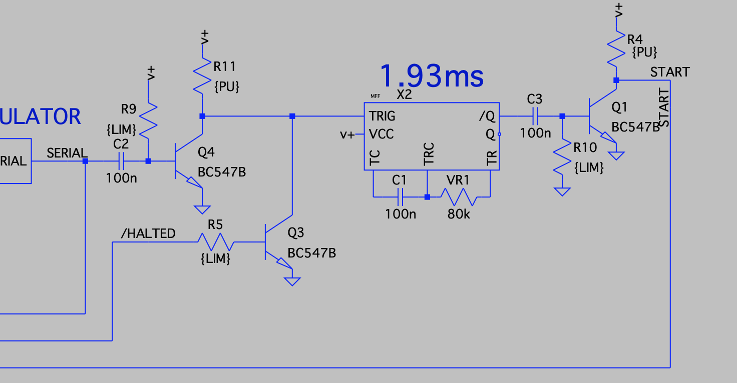
Each byte in the serial bit stream have a initial zero-startbit, this startbit is used to startup the 300Hz clock generator. But we really can't have it start the clock at the leading edge of the pulse, we must wait for 1.5 bit times so we're in the middle of the first data bit. Then we can sample that bit immediately. Then at the next tick of the clock we're in the middle of the next bit.
There's not many parts for this PCB so it's really sparse and easy to solder up.
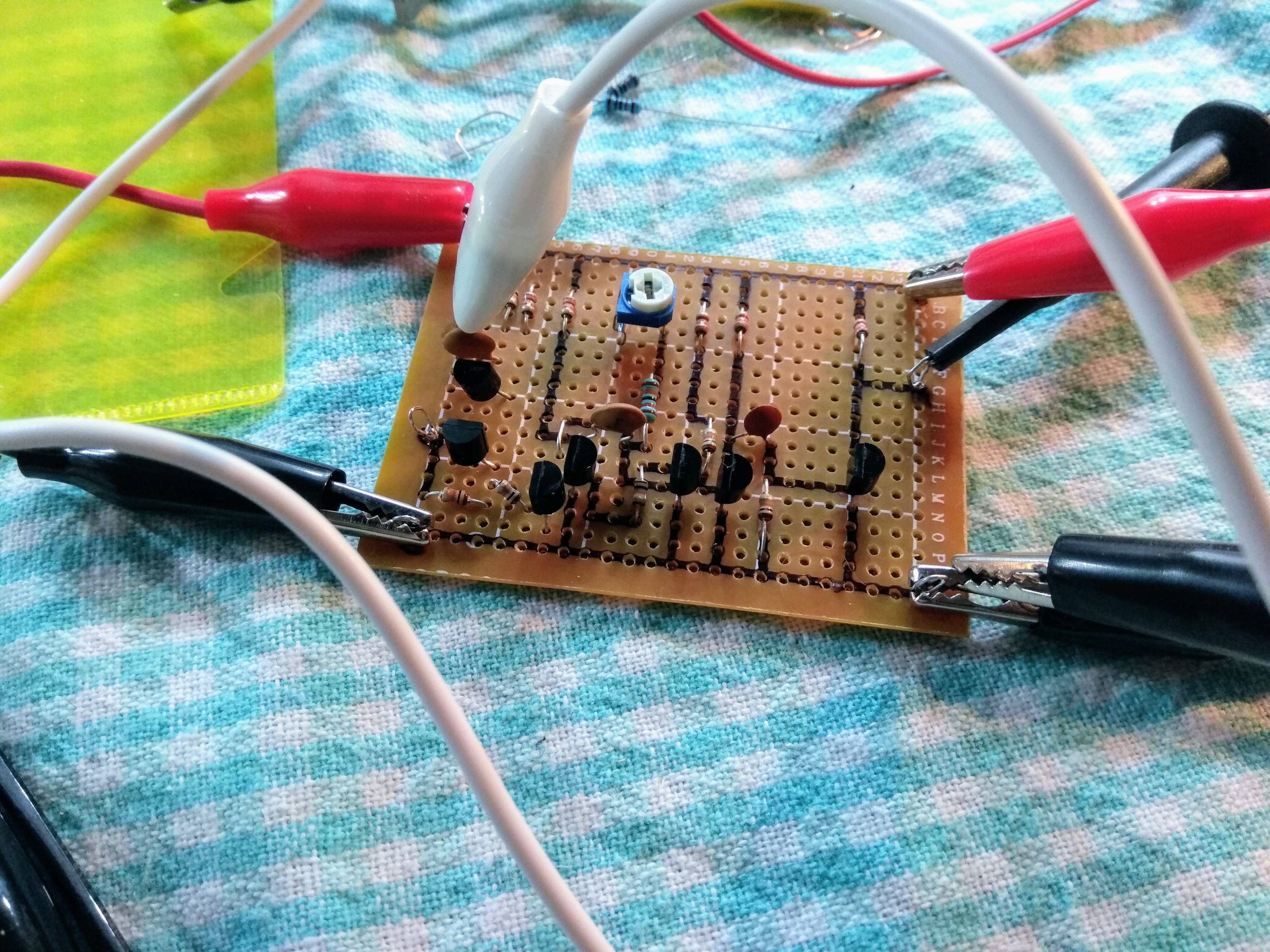
The input of the monoflop is edge-triggered and the output is also routed through a pulse shortener. So even if I give it a long input pulse I get a short outgoing pulse after the designated delay.
Ok, this seems to work as intended. Onwards to the next module.
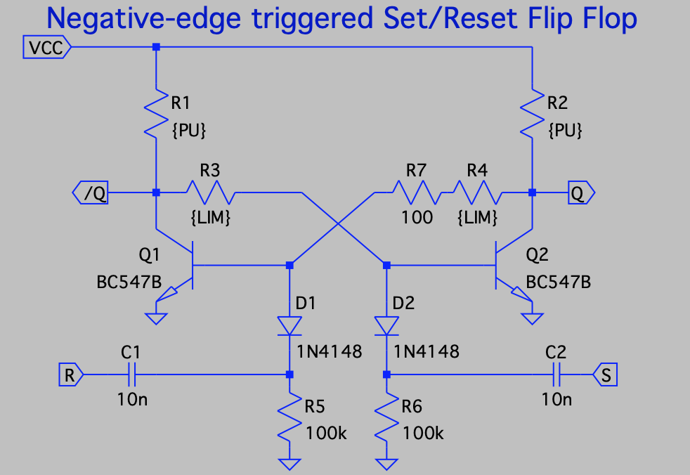
S/R FlipFlop
Next up is the Set/Reset flipclop that is set by the delayed startbit and then reset again by the last output of the ringcounter. This flipflop is controlling whether the 300Hz clock generator is running or not.
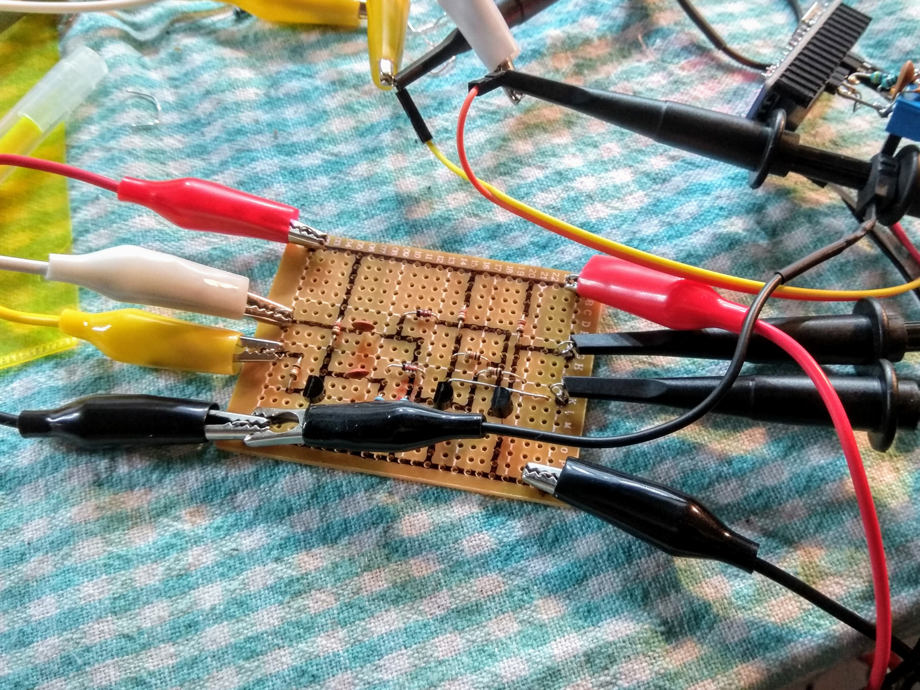
This is also a very simple PCB ans was very quick to solder up and test. I'm really happy to have a four channel oscilloscope, it makes testing of stuff like this so much easier.
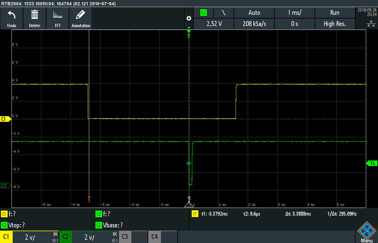
The S/R Flipflop hooked up to the oscilloscope and the arduino that generates the test signals.
 Oh yes, it is flipping and flopping as expected.
A bit of a problem
So with the clock generator, the delayer, the flopflop and the full ring counter PCBs done and tested individually it was time to connect them and test them together.
But by some reason the 3.9 ms monoflop didn't act like a monoflop, it did continously cycle acting like a astable. Even if I grounded the trigger input it still just oscillated.
After much head-scratching and beard-pulling I realized that the clock generator did inject enough hash on the power rail to retrigger the edge detector in the monoflop.

The blue line shows the VCC line up at the monostable. There's about 120mV dips in the power each time the ring counter advances.
So I hooked up a 100uF cap across the rail close to the power stage in the ring counter oscillator.

The hash didn't go away completely, but it got reduced to about 50mV which is low enough to not disturb the monoflop.
Good enough for the time being, but I probably should have both a small bulk and decoupling at each module and possibly also make a star power&ground distribution. If I ever make this into a kit I definitely will have to do that. Can't have shitty power for paying customers ;-)
Sep 27 - latches
In my original design I did some elaborate DTL NAND logic latches, but I now realized that that was too many parts to fit onto the small PCBs. I would have had to use at least four PCBs for it.
I did a redesign and came up with something simpler. Each latch have two inputs. One shared line connected to the SERIAL output from the first PCB and then a edge triggered input that is connected to the outputs of each stage in the ring counter.
So the latch stores the value of the serial line when triggered by the ring counter outputs.
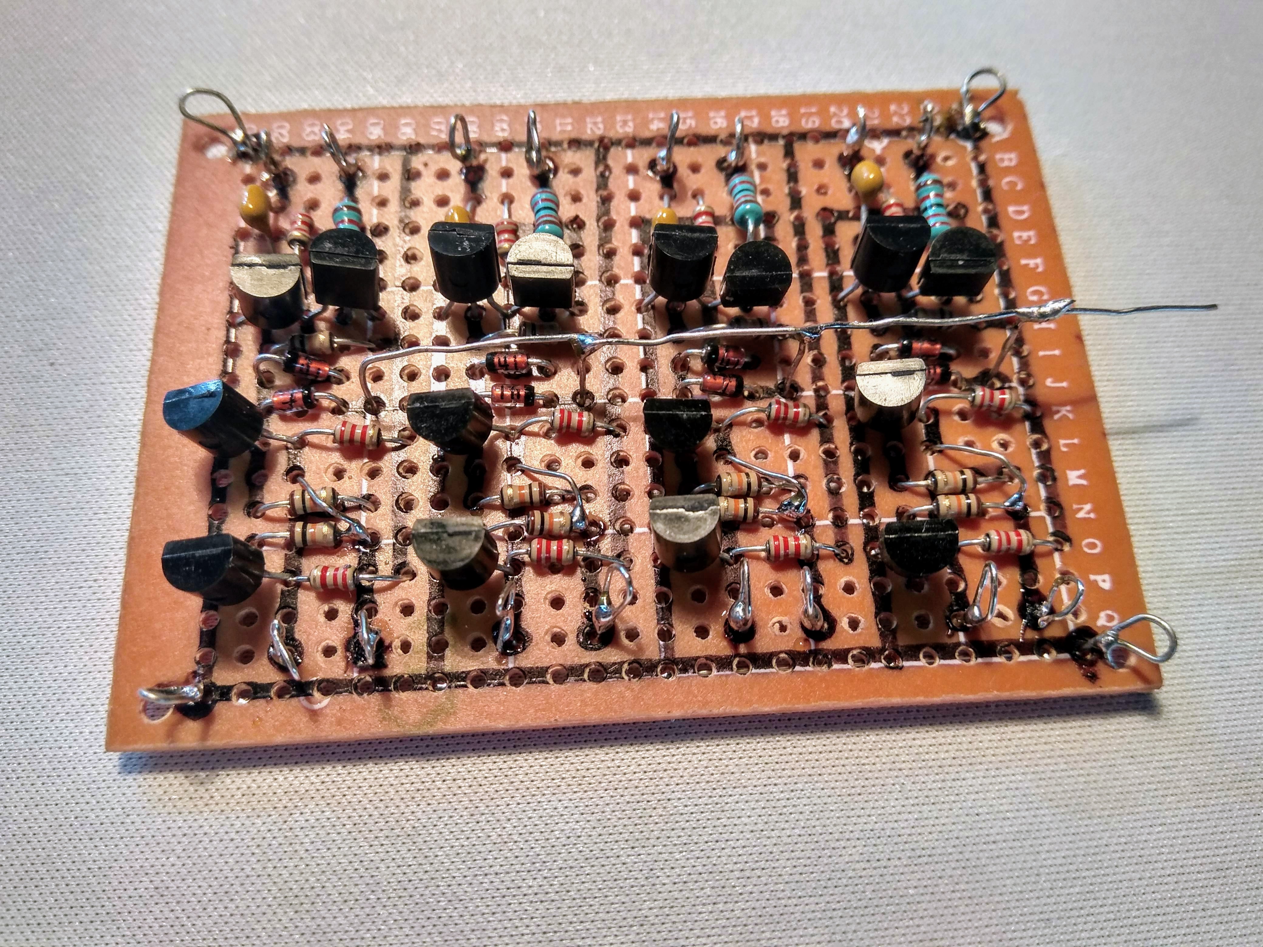
This is how the new latch looks. Easy-peasy I thought - it will be a piece of cake to fit four of those on each PCB.

Well, it turned out to be a bit cramped. I had to resort ugly things like putting the legs of two components into the same hole and using horizontal buses above the parts as well. But ok, why not as long as it works. This isn't a beauty contest...
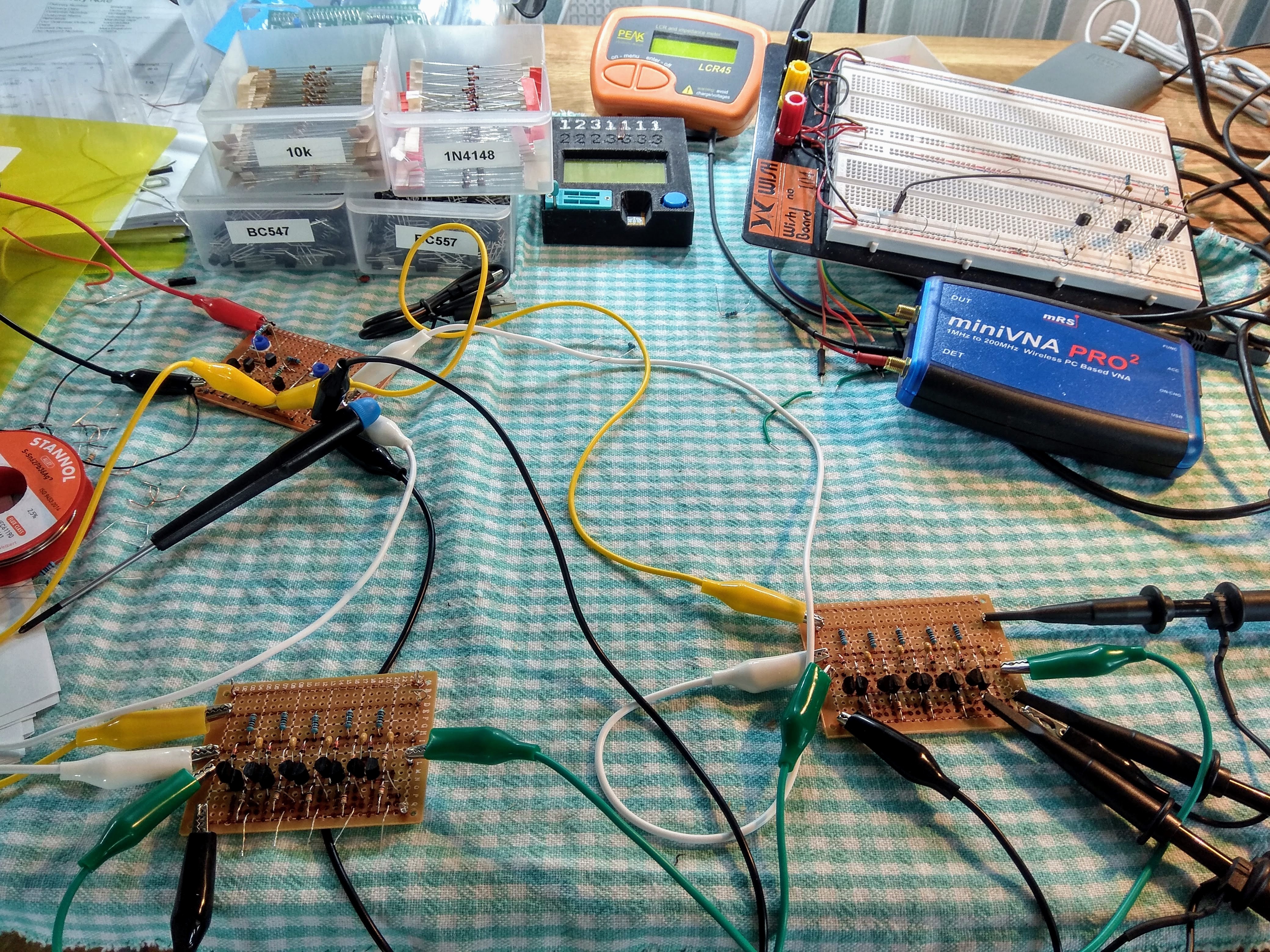
Time for some full integration testing of the entire system. Some conenction points have soldered wires and some are still with alligator clips. It kinda worked, but the ring counter was very finicky and didn't really want step properly.
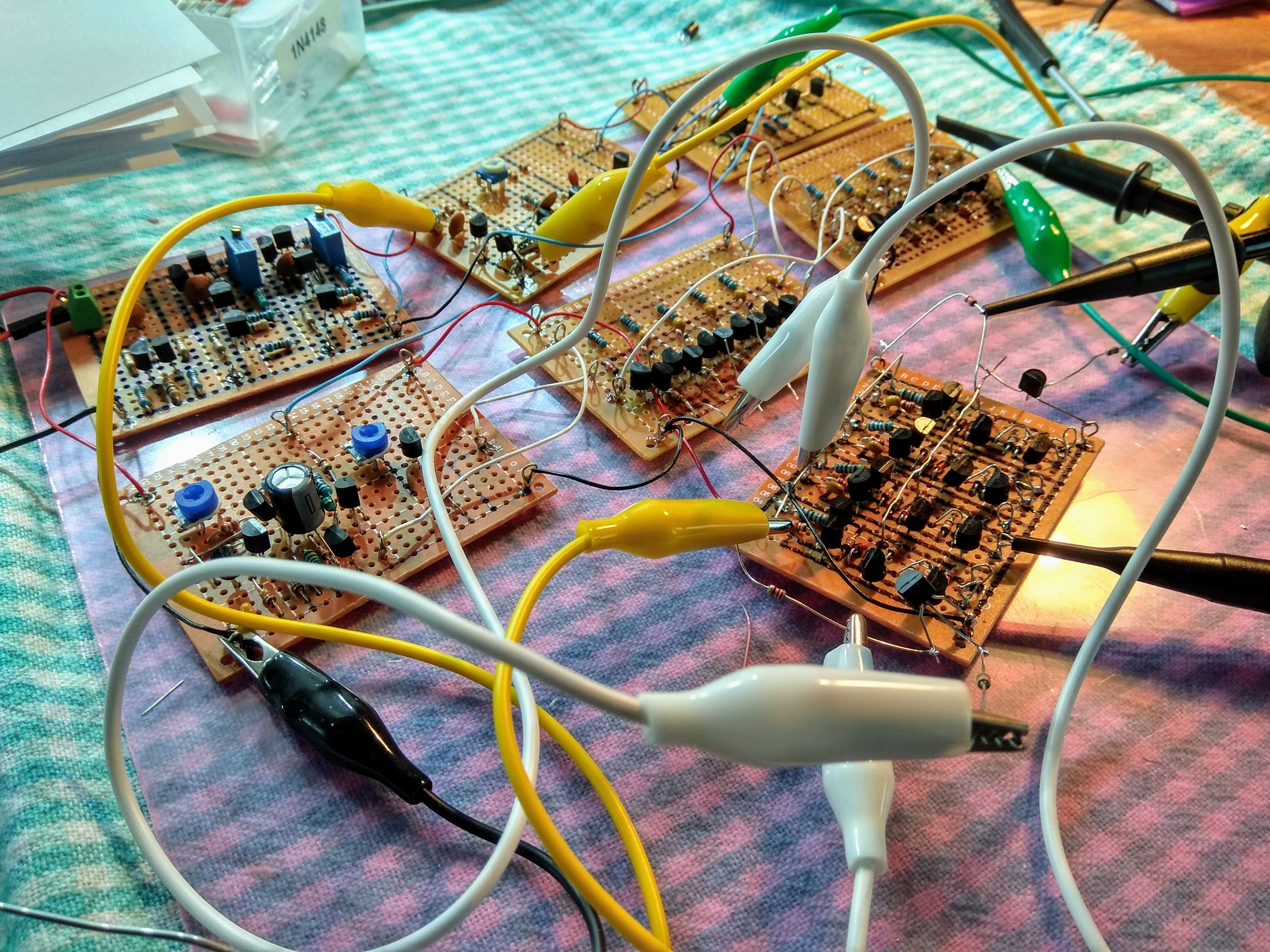
It turned out that the pulse-shortening input stage of the latches loaded down the unbuffered outputs at the ring counter stages. So I had to patch on a thin extra PCB between the ring counter pcb and the latch pcb.
At the same time I had to change the output on the ring counters from Q to /Q since the buffer pcb did invert the signals. That was easy enough since I had both outputs next to each other on the pcb.

After this it worked just fine - at least with using the pwm-sine output from the Arduino.
Tape recorder
Tape recorders seems to be a thing of the past. Even CD players seems to be a bit past their prime today. I've been looking for a 70's style small mono tape recorder for a while now and found one for just $10 in a second-hand shop near me.
The reason for being so cheap was that it did't output any sound, but the mechanics seemed ok so I bought it in the hopes of being able to easily fix it. It turned out that it just contained a single single-in-line IC that handled both the pre-amplifier form the head as well as the power amplifier for the built-in speaker. It was hot to touch and dead. I ordered a replacement for it from ebay, but it hasn't arrived yet.
Luckily a friend that I told that I was looking for a tape recorder found one in her recycling garbage room in her building and grabbed it for me.
It turned out to be a new fully working device for transferring old tapes to a computer via USB. It even had a cassette tape with 70's disco music on it. Nice!
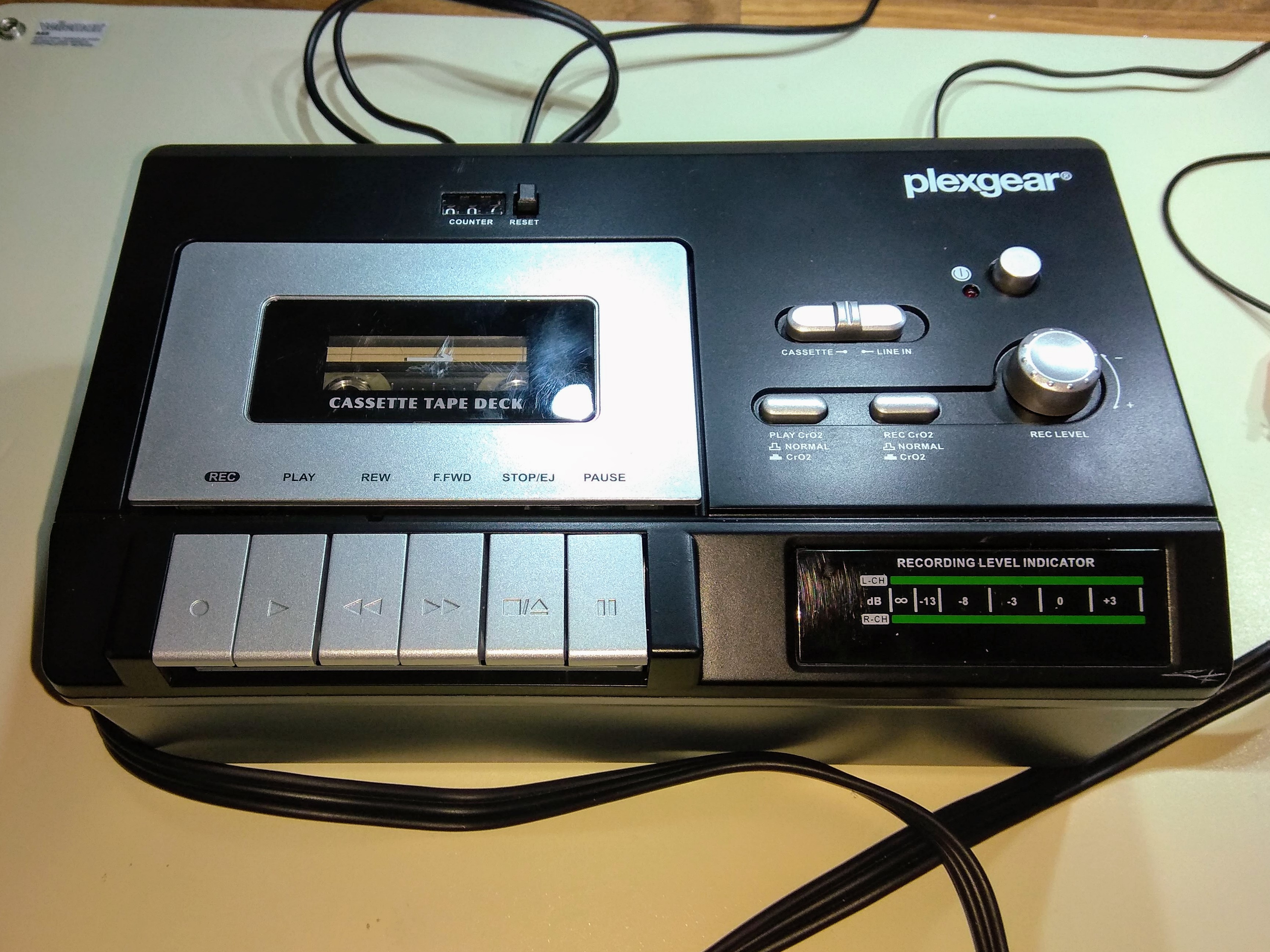
So I hooked up the arduino and recorded a minute of sound from it. Switched over the audio cables to my project and hit the play button.
IT WORKS! No problems whatsoever.
At this time I only had a couple of LEDs loosely patched into the outputs of the latches and it was past midnight. Better fix the rest of the things tomorrow. I'm happy enough as it is.
Sep 29 - Final touches
With the deadline looming just around the corner I'd better finish up the last things.
The case of the missing display
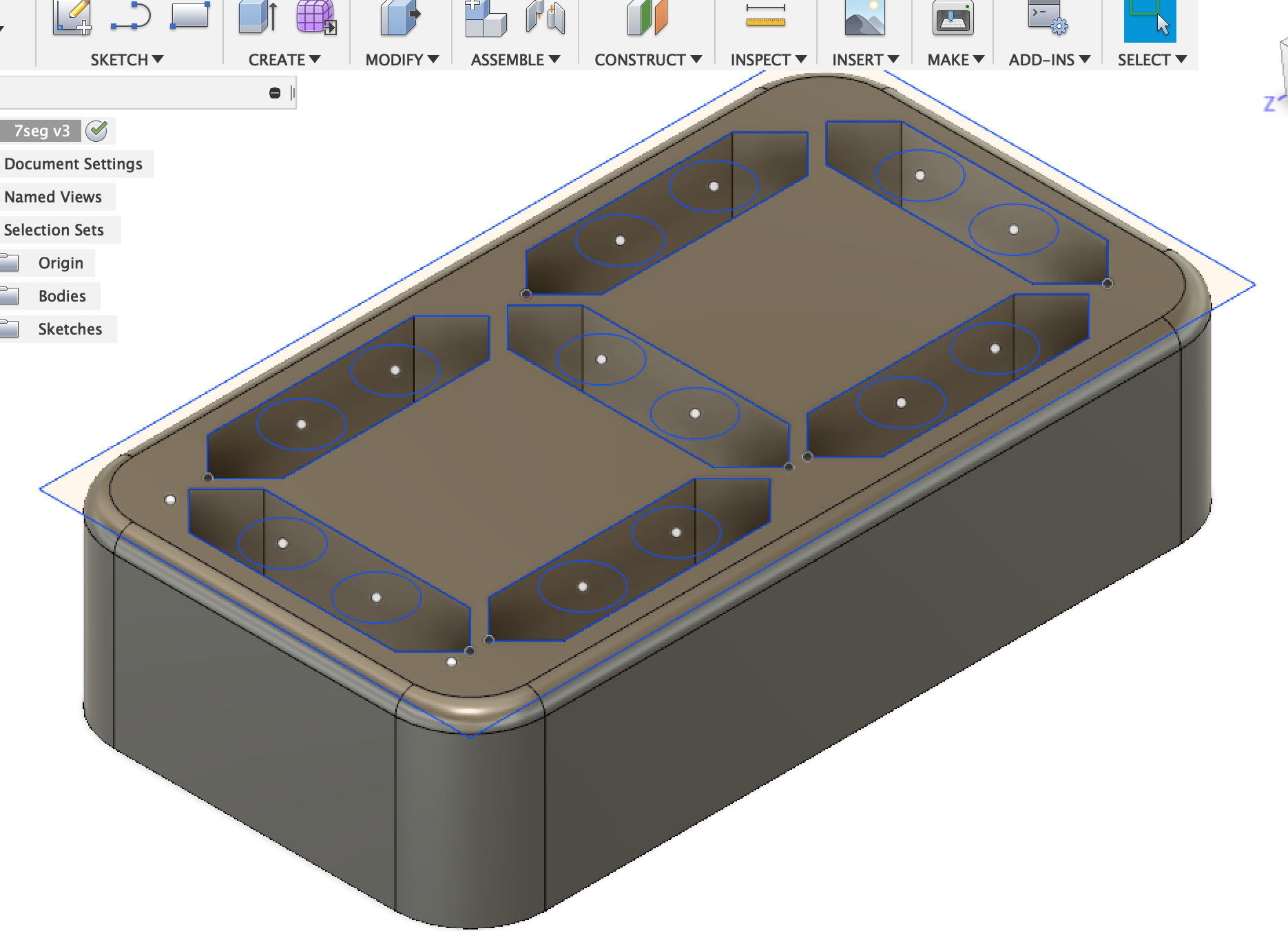
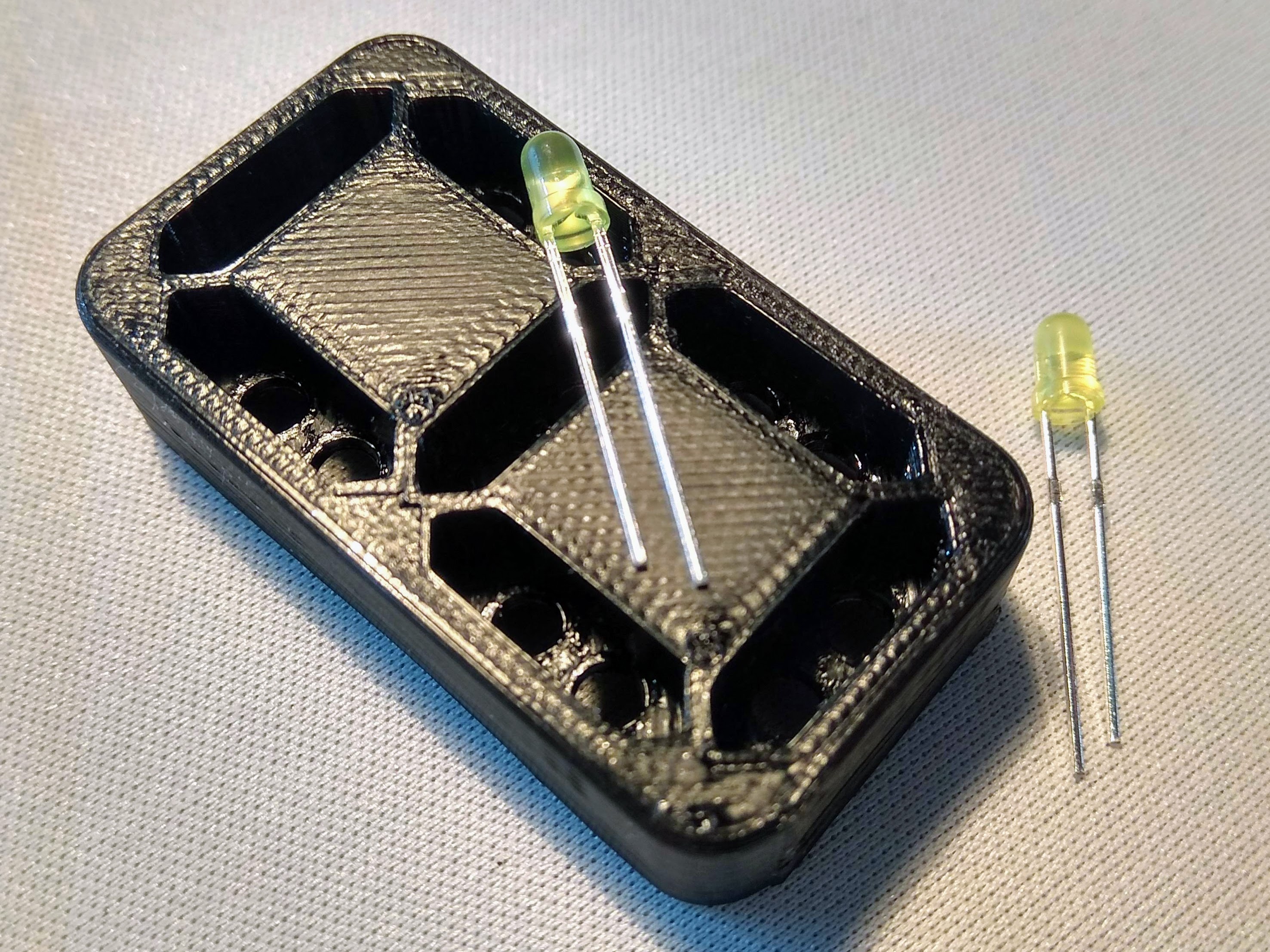
By some reason I didn't have any single-digit seven segment displays in by box of displays, but I'm the happy owner of a Zortrax M200 so I spent 20 minutes in Fusion followed by 40 minutes of printing a holder for fourteen 3mm LEDs to make my own display.
Mounting
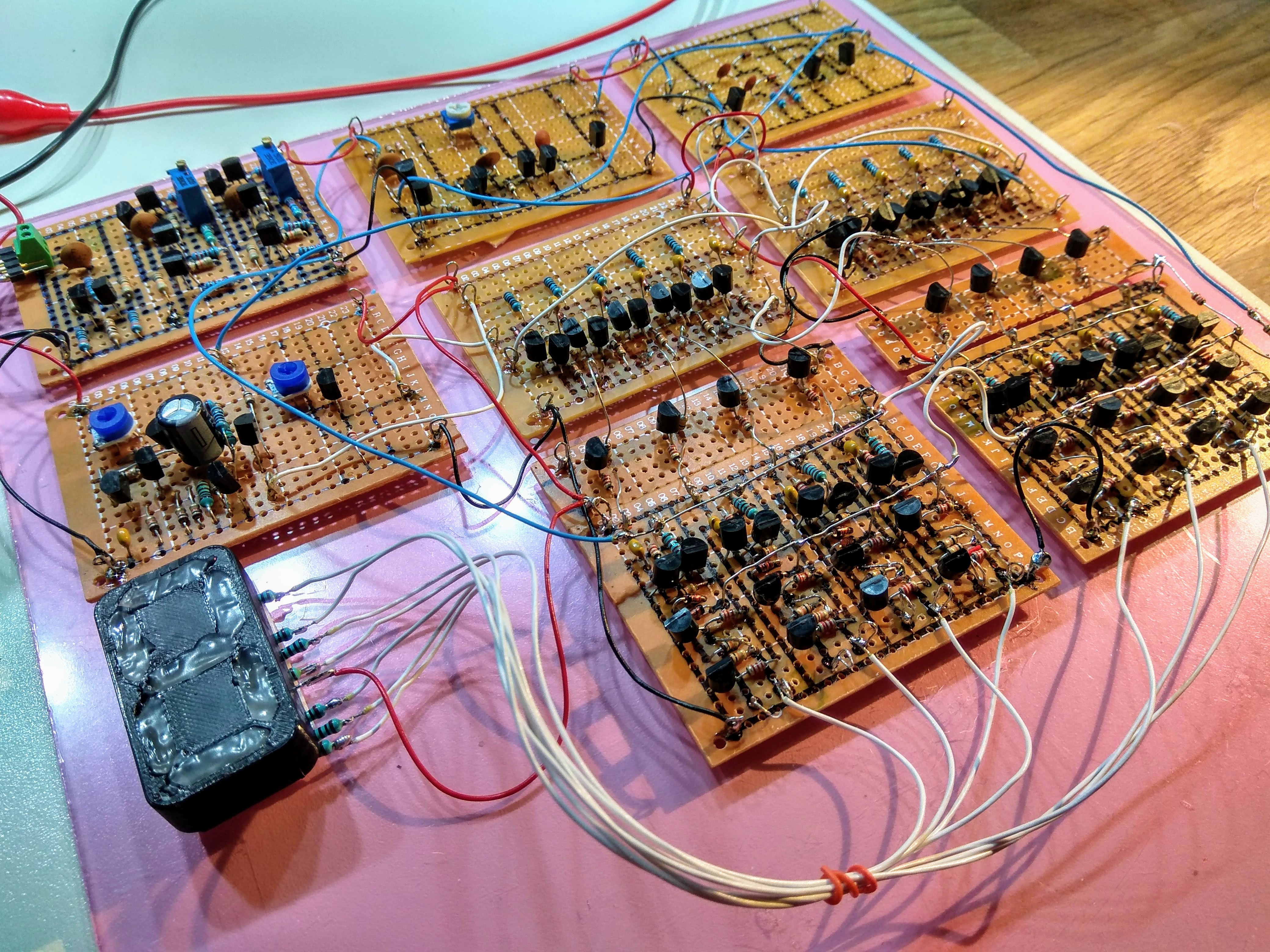
Of course I had to replace all loose wire and alligator clips with some real wiring and also tack the PCBs neatly down with double sided tape onto a piece of acrylics. I didn't bother to remove the protective plastic film from the acrylic - hence the pink tint of it.
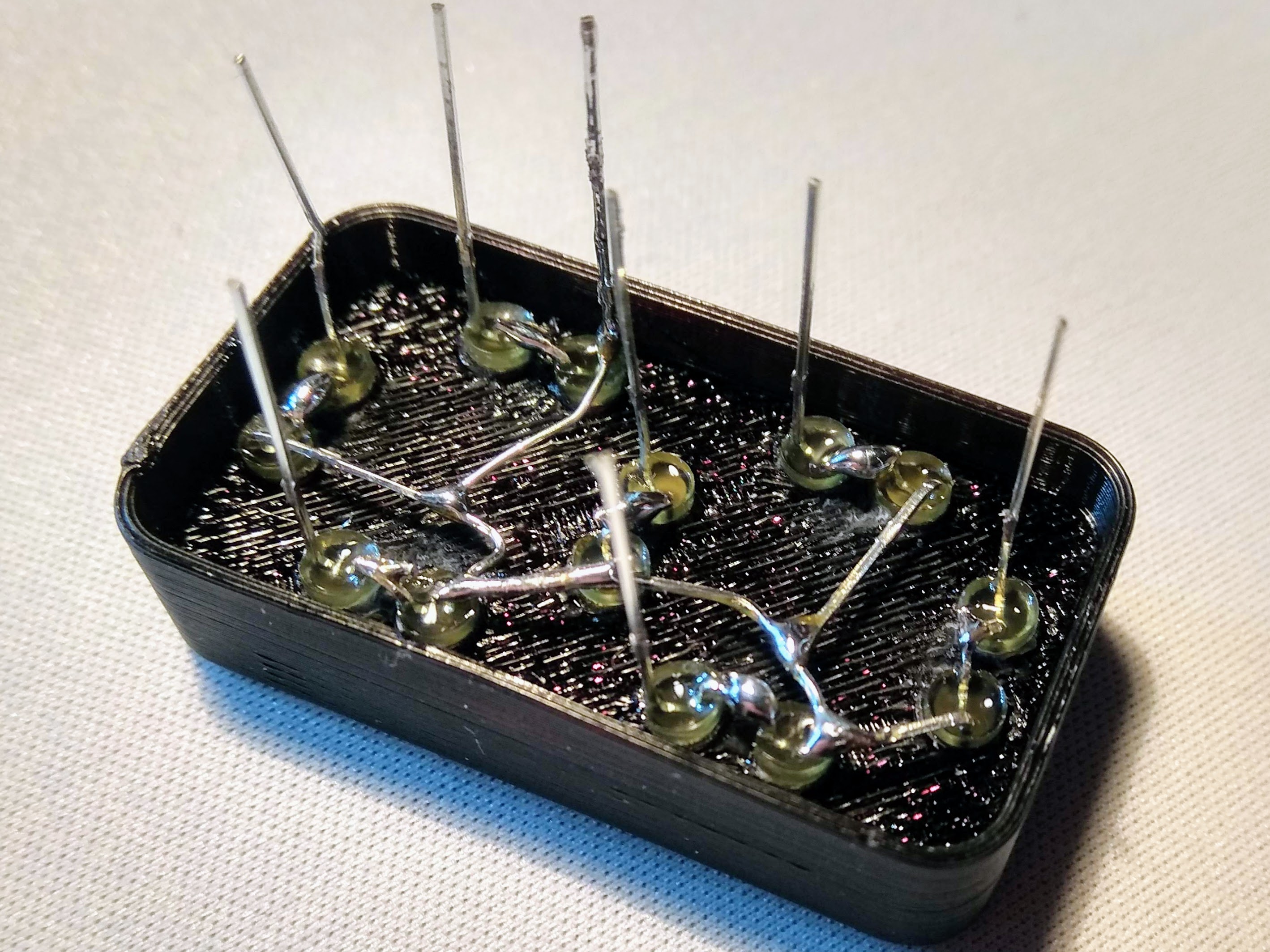
I used hot glue to fill the segment slots in the, but it turned out to be yet another thing hotsnot is not a good match for. It looks totally horrible and it doesn't diffuse the LEDs particulary well, but that's what I got for now.
Sep 30 - The video
Here's a video of the (almost) full circuit in action. I have recorded the message HELLO RETROCHALLENGE 2018-09 on the tape and is playing it back. Since the design currently lack the final latch I've encoded each character multiple times to keep the display more or less for enough time to see each character.
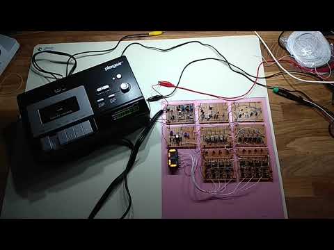
[ Click the image to play the video at YouTube ]
I'll probably will make two more cards with the missing final latch so I can hook up a HD44780 display and show a message in a more readable way, but I really think that this is good enough to show that it is not that hard to make reasonably complex stuff with only transistors.
I must admit that I'm slightly amazed that my original design made on paper and LTspice from two years back actually works and also that I had the time to pull it off during this short month.