EM7180 USFS Sensor Calibration Utilities
Introduction
Tlera Corporation offers a popular set of attitude and heading reference system (AHRS) boards known as the "Ultimate Sensor Fusion Solution" or USFS. The heart of the USFS is EM Microelectronic's EM7180 sensor fusion coprocessor, which uses PNICorp's “SpacePointTM” adaptive fusion algorithm. With proper sensor calibration, the USFS can readily provide heading accuracy of ~2deg RMS or better. The original USFS is based upon the EM7180, TDK/Invensense's popular MPU9250 9DOF accel/gyro/magnetometer chip and Bosch's BMP280 barometric pressure sensor.

This version of the USFS board has enjoyed wide acceptance by many different users for numerous applications. However, TDK has announced that the MPU9250 has reached end-of-life and production will soon cease.
Last year Tlera brought out a successor to the original USFS that is based upon the EM7180 and the latest suite of ST Micro low-power MEMS sensors.

They include the 6DOF LSM6DSM accel/gyro, the 3DOF LIS2MDL magnetometer and the LPS22HB barometric pressure sensor. Initial characterization of the ST-based USFS board shows that it delivers performance that is every bit as good (if not better) than the Invensense-based USFS. The ST-based USFS is fully pin-for-pin compatible and behaves essentially the same as the original USFS. The only differences are in the exact register writes to the EM7180 to set up output data rates (ODR's) and low-pass filter (LPF) cutoff frequencies. This is because the available accel/gyro ODR's and LPF settings do not exactly match the MPU9250 and because the ST magnetometer and baro sensors both have LPF capabilities that are not supported by the MPU9250 and BMP280. All these settings must be addressed correctly for the ST USFS to operate properly... But if they are, the performance of the ST-based version is excellent.
Sentral Coordinate System Definition
As many users already know, there are many scholarly articles and PowerPoint presentations on the internet that attempt to explain the basics of quaternions as applied to orientation estimation. Most of these references fail to deliver a set of useful transformation equations because one crucial point is neglected at the beginning: The coordinate system definition. All the transformations to go from quaternions to rotation matrices and then to Euler angles are all of the same algebraic form... But the axis indices are all potentially different because they depend upon the coordinate system definition. There are several popular coordinate system conventions used in orientation estimation. The SpacePoint algorithm in the EM7180 uses the "North, East, Down" (NED) convention that is the standard for aeronautical applications.

It should be noted that the firmware inside the Sentral rotates the individual sensor axes to conform with the NED convention. This means any given axis on any given sensor may or may not coincide with Sentral's corresponding axis, depending upon how the sensor chip is oriented on the circuit board. For example, in the photo above the PCB stencil is showing the orientation of the accelerometer's X-axis (East) while the Sentral's X-axis is actually in the "North" or forward direction. The sketches in this repository are written so the Sentral's sensor data registers are defined with respect to the NED convention.
Sentral Sensor Calibration Basics
No matter which version of the USFS is chosen, the EM7180 must be configured properly and the MEMS sensors must be calibrated correctly to obtain optimal performance. This can be readily done so that robust AHRS results are obtained but it requires proper attention to detail in both host MCU coding and sensor calibration procedures.
Accelerometers
Accuracy of the Sentral's pitch and roll estimates ultimately depends upon correcting the offsets and scaling errors of the X, Y and Z accelerometers. The Sentral's adaptive algorithm assumes that the three-axis accelerometer data are correct on their face and DOES NOT address any underlying accelerometer sensor errors. However, the EM7180 is capable of reading accelerometer error correction data from a set of input registers and applies these corrections throughout runtime. The offset and scale corrections are calculated from readings collected when each axis is aligned first parallel and then anti-parallel to gravity. As a practical matter, the USFS is aligned and held in six separate calibration orientations (X, Y, and Z aligned parallel and anti-parallel to gravity). Gravitational acceleration data are collected, averaged and stored in the on-board I2C EEPROM. These six readings are fetched from the EEPROM at startup and are loaded into the Sentral's accelerometer correction registers.
Magnetometers
Magnetometer calibration dominates heading estimation performance. Unlike the accelerometers, the magnetometers are internally calibrated by the Sentral's "SpacePoint" adaptive heading algorithm. It corrects for the "Hard iron" and "Soft iron" non-idealities of the X, Y, and Z magnetometers as well as effects from stray ferromagnetic materials and steady fields surrounding the USFS. However, for the SpacePoint algorithm to adapt, the USFS board needs to be slowly rotated throughout 3-space. You can tell when the SpacePoint algorithm has reached an adequate solution by monitoring the "Algorithm Status" byte of the EM7180. When Algorithm Status = 8 and the indicated heading is steady, the Sentral has reached "Stable calibration".
It would be rather impractical to "teach" the SpacePoint algorithm (by rotating the USFS randomly throughout all of 3-space) every time the USFS is powered up in order to get good magnetometer calibration. Fortunately, the EM7180 has a "Warm Start" feature that eliminates the need for such tedium. The EM7180 can be paused to transfer the effective parametric "state" of the SpacePoint algorithm to the on-board I2C EEPROM at any time. The same algorithm state parameters can be retrieved from the I2C EEPROM and loaded into the EM7180 at startup... So once the algorithm has "learned" and properly calibrated the magnetometers, that information can be stored and then restored every time the EM7180 is initialized.
Gyroscopes
Gyroscope calibration is by far the simplest as it requires no effort on the part of the user. The Sentral does not attempt to correct for gyroscope scale errors but it does automatically correct zero-motion biases. The algorithm assesses when the USFS is not moving and uses the "At rest" data to predict and correct the individual gyroscope bias estimates Examination of the angular velocities reported while the USFS is at rest shows the bias auto-correction method works very well.
Software Feature Overview
The code in this repository consists of Arduino USFS operation/calibration example sketches for three popular types of general purpose microcontrollers:
- Tlera "Dragonfly" and "Butterfly" Arduino-programmable STM32L4 development boards
- Tlera ESP32 Arduino-programmable development board
- Teensy 3.X family of Arduino-programmable development boards
There are both Invensense and ST specific USFS examples for each type of microcontroller. All of the sketches are intended to be as similar to each other as possible. Any differences are necessitated by feature differences of the sensors and microcontrollers. Important features include:
- All communication with the USFS (including the on-board EEPROM) is accomplished by I2C bus. The I2C clock speed is typically 400kHz
- The main loop is data-ready-interrupt driven; the interrupt is triggered when the highest output rate (gyroscope) data is ready. The Sentral's "Event status" register is polled when the interrupt is triggered to determine what other new data may be available
- By default the Sentral reports calibrated sensor data. That also means that the individual sensor axes are reported conforming to the "North-East-Down" (NED) sensor orientation convention. So for example, the "X" axis accelerometer data reported by the Sentral may not be from the "X" axis data register of the accel/gyro chip, depending on how it is oriented on the USFS circuit board...
- By default the sentral reports the AHRS estimate as NED unit quaternion coefficients. Euler angles (Yaw, Pitch and Roll) are calculated from the quaternion coefficients using standard NED-based transformations
- The barometric pressure sensor reports both the ambient temperature and barometric pressure, largely for demonstration purposes
- The Sentral "Algorithm status" byte is reported to show when the SpacePoint algorithm has relaxed to "Stable calibration" during magnetometer calibration
- Loop cycle time is reported in us and the serial monitor is updated at a default rate of 10Hz. The loop cycle time will fluctuate between ~3-5us (no data ready) and ~1300us (accel, gyro, mag, baro and quaternion data all ready)
- Accelerometer calibration and warm start parameter save functions can be triggered at will over the USB serial monitor
- Warm start parameters and accelerometer calibration data are stored in the I2C EEPROM on the USFS board. They are read at startup and checked for validity; if valid, the data is loaded into the Sentral and the calibration corrections are applied
Software Operation and Calibration Instructions
Basic Operation and Screen Messaging
- Select the appropriate sketch for your microcontroller development board (STM432L4, ESP32 or Teensy 3.x) and USFS board (Invensense or ST sensors). A word to the wise: Running an ST USFS with an Invensense sketch (or the other way around) WILL NOT WORK. Either the sketch will hang or the AHRS data will be nonsense
- Follow the hardware-specific interconnection instructions in the "Readme.md" file for the specific sketch you have chosen. Build/upload the sketch from the Arduino IDE. Power-cycle the board and open the Arduino serial monitor (or any terminal emulator you prefer)
- You should see a startup sequence on the Arduino serial monitor similar to fht following screen capture:

- The accelerometer calibration data are displayed as part of the Sentral startup procedure. The data are in ADC counts where 1g = 2048. If all three accelerometers were perfect, maxima and minima would all be +/- 2048, respectively. If any of the data vary more than +/-~10% from their target values, the entire calibration is judged as invalid and is not loaded into the Sentral.
- When the Warm Start parameters are retrieved from the EEPROM, the final byte of the sequence is a "Validation byte". This byte is erased immediately before Warm Start data is written to the EEPROM and is re-written once Warm Start data is successfully saved. This byte is checked at startup; if the value is correct, the Warm Start parameter data is loaded into the Sentral. Otherwise, Warm Start parameters are not loaded into the Sentral and will be reflected in the startup screen messaging. Once Sentral Startup is complete, the main loop will start running and sensor/AHRS data will stream across the Arduino serial monitor as shown in the following screen capture:
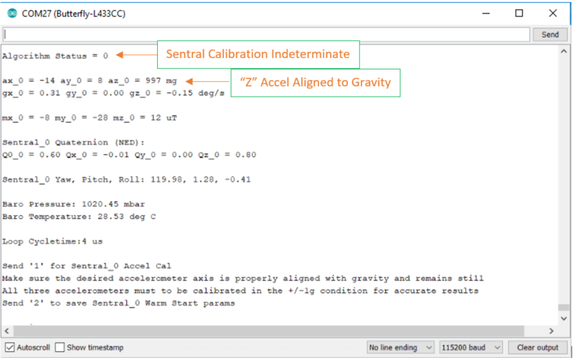
- In this serial monitor screen capture, the "Algorithm Status" field is highlighted. It will initially assume a value of "0" when the USFS first starts up and has not experienced any significant motion
- The balance of the update screen includes:
- X, Y, and Z accelerometer data in milli-g's (mg)
- X, Y, and Z gyroscope data in degrees per second (deg/s)
- X, Y, and Z magnetometer data in micro-Teslas (uT)
- Unit quaternion coefficients (dimensionless)
- Euler angles (Yaw, Pitch and Roll) in degrees
- Barometric pressure in milli-bars (mbar)
- Ambient temperature in degrees Celsius (deg C)
- Loop cycle time in microseconds (us). The loop cycle time will fluctuate significantly because it is dominated by I2C data transfer time for whatever new data is available at any given cycle of the loop...
- The accelerometer data is also specifically highlighted in this screen capture as this data is crucial for the accelerometer calibration procedure. In this example, the Z-accelerometer is aligned parallel to gravity; az ~ 1000mg and ax, ay <+/-30mg. This orientation of the USFS would be satisfactory for collecting the "Z-acc max" accelerometer calibration data to be stored in the EEPROM...
- Next, randomly rotate the USFS throughout 3-space while taking note of the "Algorithm status" byte:

- When this byte toggles from "0" (Indeterminate) to "8" (Calibration stable) the SpacePoint algorithm should be converged to a stable operating point
- Assuming the accelerometers and magnetometers have already been calibrated, the USFS can now be used for accurate attitude estimation. If not, proceed to the next section...
Accelerometer Calibration
Once proper operation of the USFS has been verified, typically it is a good time to calibrate the accelerometers. To avoid confusion, let's state up front that the "Sentral Accel Cal" function will be executed a total of six times from the Arduino serial interface to collect all the data for a valid accelerometer calibration. The accelerometer calibration function is written specifically to:
- Automatically determine which axis (X, Y, or Z) and which gravity alignment condition (parallel or anti-parallel) is being calibrated
- Collect and average 512 raw acceleration readings for the axis being calibrated
- Test that the absolute value of the new averaged calibration reading is within +/-~10% of 1g
- Only save the one new calibration reading to the EEPROM and only if it is valid
Alignment of the USFS during the six individual accelerometer calibrations is typically accomplished using a "Third hand" flexible universal holding fixture as shown below:

Be sure to cover the jaws of the metal clamps with insulating material (such as one or more layers of heat-shrink tubing) to keep from shorting out any circuitry on the microcontroller/USFS boards. Caution should be exercised to avoid mechanically damaging any components on either of the circuit boards. Now that we have a means of safely holding the USFS in any desired orientation, the remainder of the accelerometer calibration is straightforward:
- Start with the X-axis in the +1g condition
- Orient the USFS so that the X-axis accelerometer reads its maximum positive value and the orthogonal (Y-axis and Z-axis) accelerometers read <+/-30mg
- Send a "1" over the Arduino serial interface
- It will only take a few seconds for the microcontroller to collect, average and store the data to the EEPROM
- Re-orient the USFS so that the X-axis accelerometer reads its maximum negative value and the orthogonal accelerometers read <+/-30mg
- Send a "1" over the Arduino serial interface and wait for the data to be collected and saved to the EEPROM
- This completes calibration data collection for the X-axis accelerometer
- Repeat this procedure for Y-axis +1g, Y-axis -1g, Z-axis +1g and Z-axis -1g to complete accelerometer calibration for the Y and Z axes. Remember to maintain the readings on the two orthogonal axes to be <+/-30mg
- Next, power-cycle the microcontroller/USFS for the new calibration to take effect and open the Arduino serial monitor. You should now see six new accelerometer calibration values in the startup screen
- When the main loop starts running, you should see that the accelerometers now read within a few mg of "+/-1000" when aligned to gravity
- If one or more of the axes does not meet your accuracy expectations, simply repeat the calibration procedure for that axis and re-check the results...
Magnetometer Calibration
Sentral magnetometer calibration is quite simple but a few key points should be kept in mind:
- Accelerometer should be done first. It is best if the accelerometers have been calibrated and the board has been power-cycled (for the accelerometer calibration to take effect). Although accelerometer data may not be explicitly part the heading algorithm, they are used to assess the pitch and roll tilt conditions of the magnetometers. If the accelerometers have not been calibrated, the systematic errors can degrade the effective magnetometer tilt compensation potentially causing the practical heading accuracy to suffer
- Stray magnetic fields make a difference. Remember, the geomagnetic field strength is only about 25 - 65uT. Many modern electronic devices can generate stray fields that are significant with respect the earth's magnetic field. Being too close to running computers, video monitors, etc. can cause the SpacePoint algorithm to adapt in a way that degrades heading accuracy. Typically, one should be about 3-5 feet from any computers/monitors or other stray field generating devices to perform USFS magnetometer calibration
- Ferromagnetic materials in the immediate vicinity of the USFS make a difference. Having steel fasteners near the USFS will induce soft iron distortion into the magnetometer response characteristics. This is not the end of the world as the SpacePoint algorithm can correct for these effects. However, if possible, magnetometer calibration should be done with the USFS installed in the environment/vehicle where it will be operating. In cases where the USFS can't be freely rotated in 3-space while installed (i.e. the vehicle to which it is attached is too heavy to pick up and twirl around hy hand) care should be taken to limit changes in the ferromagnetic materials immediately surrounding the USFS after magnetometer calibration
- The USFS must be rotated randomly in 3-space during magnetometer calibration for the SpacePoint algorithm to converge to the correct operating state. Placing the USFS on a flat surface and rotating in the X-Y plane will not yield satisfactory results. Remember, the magnetometer has THREE axes because the geomagnetic field and the USFS will not be limited to the X-Y plane. The Z-axis magnetometer response needs to be just as accurate as the X-axis and Y-axis responses. Why? If not, changes in the earth's magnetic dip angle and/or changes in the USFS's pitch/roll attitude would cause erroneous heading estimates. This video post shows a magnetometer being randomly rotated in 3-space while a PC monitor maps out the X,Y,Z magnetic response surface. This type of full 3D rotation is best for Sentral magnetometer calibration...
Once the accelerometers have been calibrated and you have verified that the USFS's immediate environment is suitable for magnetometer calibration:
- Power up the microcontroller/USFS and open the Arduino serial monitor
- Monitor the "Algorithm Status" field. It should initially be "0", which means the SpacePoint algorithm has insufficient data to determine the quality/stability of its current state
- Rotate the USFS throughout 3-space as described above. You should see the "Algorithm Status" field toggle to "8". This means the SpacePoint algorithm has achieved "Stable calibration"
- As an initial check, hold the USFS level and right side up. Note the value of Z magnetometer (mz). Now hold the USFS level and upside down. The value of mz should be within a few uT of the right side up value and of opposite sign. If this is not true, continue randomly rotating the USFS in 3D until you see the best agreement of |mz| in the right side up and upside-down conditions
- When the SpacePoint algorithm is in the process of final adjustment, the indicated heading can slowly evolve even though the USFS is stationary. Hold the USFS level, right side up and at a stable heading. Observe the heading ("Yaw") value for a minute or so. If it is stable, magnetometer calibration is complete. If the heading is slowly drifting, allow it to relax until it becomes stable
- Now, simply send a "2" over the Arduino serial monitor. The Warm Start parameters will be polled from EM7180 and stored in the EEPROM. During this process, serial data updates will stop briefly and then resume when the EEPROM write is complete
- After power cycling, the USFS should behave as it did immediately after the calibration process was completed
Software Adjustable Features: "config.h" Overview
The sketches in this repository have a certain degree of feature adjustability that is set by parameter definitions in the "config.h" header file. In general, these parameter definitions should only be adjusted with care. This section will describe the adjustable performance features and offer some guidance for their adjustment. Wherever possible, there is a "pick list" of supported options for each parameter category. UNCOMMENT ONE OPTION PER LIST ONLY. The specific entries in each pick list reflect the allowed parameter values for the individual sensors.
I2C Bus and Basic Pin Assignments
- SENSOR_0_WIRE_INSTANCE: This definition specifies which of the microcontroller's available I2C busses will be used for the USFS. For the STM32L4 and ESP32 development boards, there are several possibilities. For the Teensy 3.X only the primary I2C bus is listed. There are supplementary definitions for the I2C SCL and SDA pin specifications, if necessary.
- LED_PIN: Defines the GPIO pin for the on-board indicator LED. Refer to your microcontroller documentation for any alternative choices
- INT_PIN: Specifies the Sentral data-ready-interrupt GPIO pin. Any GPIO capable of supporting an external interrupt can be used
- UPDATE_PERIOD: Defines the serial monitor update period in milliseconds. The default is 100ms or 10Hz
Sensor Output Data Rates (ODR's)
- ACC_ODR and GYRO_ODR: Usually the accel and gyro ODR's are matched and are the fastest. 800-1000Hz is typical. The ST accel/gyro will go up to 1660Hz but this ODR causes the SpacePoint algorithm to struggle with maintaining "Stable Calibration"...
- MAG_ODR: Typically 100Hz; this works quite well for general purposes
- BARO_ODR: 25-50Hz is typical
- QUAT_DIV: This is the Sentral's "Quaternion divisor" factor. The quaternion ODR is simply (Gyro ODR)/(QUAT_DIV + 1). The Sentral can deliver quaternion ODR's ah high as 400Hz. However, a quaternion ODR of ~100Hz is typical
Sensor Scales
- ACC_SCALE: +/-2g - +/-16. +/-8g is typical. +/-16g is appropriate for UAV's
- GYRO_SCALE: For Invensense sensors the range is +/-250 - +/-2000DPS while for ST sensors the range is +/-125 - +/-2000DPS. +/-2000DPS is typical and is also appropriate for UAV's
- MAG_SCALE: The magnetometer scales are not variable but differ between the two sensor sets. For Invensense it is +/-1000uT while for ST it is +/-4915uT
Low-Pass Filter (LPF) Settings
The low-pass filters remove high-frequency noise from the sensor data streams going into the Sentral but also induce sensor phase delay. This tradeoff between noise suppression and phase delay is typically done by trial-and-error. The Invensense sensor set only offers LPF's for the accelerometers and gyroscopes. The ST sensor set offers these plus LPF's for the magnetometers and barometric pressure sensor. The entries in the LPF cutoff frequency pick lists range from least aggressive to most aggressive.
Sentral Calibration Management
As described in an earlier section, the stored accelerometer calibration and Warm Start parametric data is tested for validity when it is retrieved from the EEPROM and before it is loaded into the EM7180. However, in some instances the user may wish to suppress loading of the accelerometer calibration and/or Warm Start parameters. The "ACCEL_CAL" and "SENTRAL_WARM_START" definitions are used to activate or deactivate automatic loading of valid calibration data. By default, they are defined as "1" to activate calibration data loading. Either or both can be defined as "0" to suppress calibration data loading.
Magnetic Declination
Finally, to provide accurate heading the magnetic declination for your location needs to be defined. Simply look up your magnetic declination and define "MAG_DECLINIATION" as a floating point constant in decimal degrees.