👇 captouch - Capacitive Touch Buttons for any FPGA!

Rationale I was thinking about adding a capacitive touch interface to the
NEORV32 RISC-V Processor. A software library (something like Microchip's
QTouch
Overview
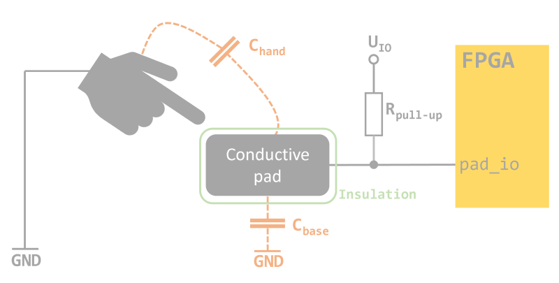
The captouch capacitive touch controller allows to convert any FPGA's IO pin into a capacitive push button.
If a finger gets close enough to a touch button the controller recognizes this by a change of capacitance.
The button status output is filtered to provide reliable operation without metastability. Via an internal
calibration process, which can be re-triggered any time, the controller automatically adapts itself to setup's
electrical characteristics.
The controller can operate in stand-alone mode (imagine a tiny Lattice iCE40 FPGA turned into a multi-channel touch controller), as controller for custom logic or as fancy user interface attached to a soft-core processor system.
Electrical Requirements
The capacitive buttons ("pads") need to be made from conductive material like PCB copper areas coated with solder mask. Each pad requires an individual pull-up resistor (~1M Ohm) that connects the pad to the FPGA's IO supply. Any FPGA pin can be used as pad interface as long as the pin supports tri-state bi-directional functionality.
Example Setup
My test setups implements 3 capacitive buttons. Each button is tied to the IO supply (3.3.V) via 1M pull-up resistors.
The actual pads are made from kitchen aluminum foil wrapped around bare copper wires and are insulated with two
layers of Tesafilm (transparent Scotch Tape). The FPGA is an Intel Cyclone IV running at 100MHz. The four left-most LEDs
are used to display the captouch controller status: "calibration done" status (ready_o) on the far-left followed by three
LEDs showing the current touch button states (touch_o).
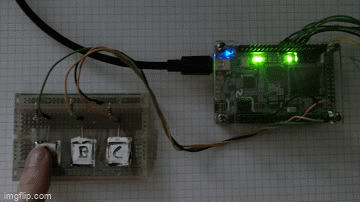
(gif made with imgflip)
Note that this is not(!) an optimal setup.
Mapping results for an Intel Cyclone IV EP4CE22F17C6 FPGA using 3 capacitive buttons (NUM_PADS = 3):
Logic Cells:               145
Dedicated Logic Registers:  78
Theory of Operation
The controller uses the fact that greater capacitors need more time to charge when powered by a limited current source (which is a very high pull-up resistor in this case). The touch pads serve as variable capacitors in this setup. If there is no finger next to them they have a fixed base capacitance defined by the conductive pad area (and it's surroundings). If a finger comes close to a pad the finger acts as additional electrode increasing the pad's capacitance.
As an illustration the following (crappy) image shows two exemplary charging curves: The curve reaching the IO buffer's
trigger voltage U_trig at time T_base represents a touch pad with no finger close to it. The second curve that reaches
U_trig at T_pushed represents a "pushed" capacitive button. U_IO is the supply voltage of the FPIO IO bank that is
used to connect the capacitive pads.
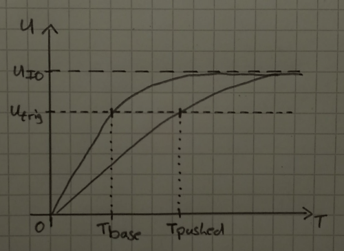
The time it takes to charge a pad back to U_IO is defined by the capacitance of the pad (the electrode area) and the
pull-up resistor. The pad's potential (charging level/voltage) is an analog value that is turned into a digital value
by the hysteresis of the FPGA's input buffers. Internal synchronization registers make sure there is no metastability left.
The controller measures the time until a discharged pad (temporarily tied to ground) takes until it is charged to the supply voltage. After reset, the controller enters calibration mode. It discharges all pads first and initializes an internal counter to zero. After that, the pad's FPGA pins are switched to input mode. Now the pads charge via the external pull-up resistors. As soon as all pads are charged, the controller stops the time measuring counter and leaves calibration mode.
The counter state, which indicates the required sample cycles until all pads were fully charged, is used to compute
a threshold. The computation is configured by the SENSITIVITY generic. Based on this generic,
the controller adds a certain offset to the counter value, which results in the final threshold. Basically, this offset
represents the additional capacitance (your finger) required to trigger the "pushed" state of the pads. There are further
configuration options to customize the sensitivity - see section Fine-Tuning for more information.
Now controller enters normal operation mode, which is an endless loop. The loop starts again with discharging all pads. After that, the pads charge again and a counter keeps incrementing. As soon as the counter reaches the threshold value, the current state of the pads (a binary value: fully charged or not) is sampled.
Several sampling results are stored into a buffer to stabilize ("filter") the current pad state. This final pad state is output and indicated whether a capacitive button is "pushed" or not.
Top Entity
The top entity is captouch (rtl/captouch.vhd).
It can be instantiated right away - no special/device-specific libraries are required at all.
entity captouch is
  generic (
    F_CLOCK     : integer; -- frequency of clk_i in Hz
    NUM_PADS    : integer; -- number of touch pads
    SENSITIVITY : integer  -- 1=high, 2=medium, 3=low
  );
  port (
    -- global control --
    clk_i       : in    std_ulogic; -- clock
    rstn_i      : in    std_ulogic; -- async reset, low-active
    rstn_sync_i : in    std_ulogic; -- sync reset, low-active
    -- status --
    ready_o     : out   std_ulogic; -- system calibration done when high
    touch_o     : out   std_ulogic_vector(NUM_PADS-1 downto 0); -- touch pads state
    -- touch pads --
    pad_io      : inout std_logic_vector(NUM_PADS-1 downto 0)   -- capacitive touch pads
  );
end captouch;std_ulogic/std_ulogic_vector except for the bi-directional tri-state
capacitive pad interface that is of type std_logic_vector (resolved type; only relevant for simulation).
F_CLOCK should be greater than the internal pad sampling frequency
(see Fine-Tuning).
Configuration Generics
| Name | Type | Description |
|---|---|---|
F_CLOCK |
integer | clock frequency of the clk_i input signal in Hz |
NUM_PADS |
integer | number of capacitive pads to implement (min 1) |
SENSITIVITY |
integer | sensitivity level (1=high, 2=medium, 3=low) |
The SENSITIVITY level defines the minimum required increase of the pad's capacitance (C_base + C_hand (=finger))
in order to detect the button as "pushed":
- high: +6.25%
- medium: +12.5%
- low: +25%
Interface Signals
| Name | Direction | Width | Description |
|---|---|---|---|
clk_i |
input | 1 | main clock |
rstn_i |
input | 1 | asynchronous reset, low-active; connect this to the system's global reset network |
rstn_sync_i |
input | 1 | synchronous reset, low-active; this signal provides the same functionality as rstn_i but can also be used to (re-)trigger calibration by the application logic |
ready_o |
output | 1 | after reset is released, this signal goes high when calibration is done and the controller enters normal operation mode |
touch_o |
output | NUM_PADS |
state of the according touch pad (0 = not pushed, 1 = pushed) |
pad_io |
bidirectional | NUM_PADS |
capacitive touch pads, each pad requires an individual pull-up resistor |
ready_o and touch_o) are synchronized to the input clock (clk_i).
Fine-Tuning
The VHDL source file provides additional configuration constants for fine-tuning:
-- configuration --
constant f_sample_c    : integer := 3300000; -- pad sample frequency in Hz
constant scnt_size_c   : integer := 11; -- pad sample counter size in bits
constant f_output_c    : integer := 10; -- max output state change frequency in Hz
constant filter_size_c : integer := 3; -- output filter size in bits| Constant | Default | Description |
|---|---|---|
f_sample_c |
3300000 (3.3MHz) | Pad sample frequency |
scnt_size_c |
11 (bits) | Pad sample time counter width, increments with f_sample_c |
f_output_c |
10 (10Hz) | Maximum frequency the final output touch_o can change per second |
filter_size_c |
3 (bits) | Number of PAD samples used to define touch_o output state (all filter_size_c samples above threshold -> output high; all filter_size_c samples below threshold -> output low) |
f_sample_c and the sample counter width scnt_size_c define the actual resolution
of the touch controller (higher sample frequency and wider counter -> higher resolution). You might need to experiment
with these two values to find the perfect resolution for your specific pad configuration.
scnt_size_c is too small, the controller will fail calibration process (ready_o stays low).
Simulation
The projects provides a very simple testbench (to check the controller-internal states only - no simulation of
the capacitive touch pads yet) sim/captouch.vhd, which
can be simulated by GHDL via the provides script (sim/ghdl.sh):
captouch/sim$ sh ghdl.sh
The default simulation will run for 2ms using a 100MHz clock and 4 touch pads. The waveform data is stored to sim/captouch.vcd
so it can be viewed using gtkwave:
captouch/sim$ gtkwave captouch.vcd
Legal
License
This project is released under the BSD-3-Clause License.
Limitation of Liability for External Links
Our website contains links to the websites of third parties ("external links"). As the content of these websites is not under our control, we cannot assume any liability for such external content. In all cases, the provider of information of the linked websites is liable for the content and accuracy of the information provided. At the point in time when the links were placed, no infringements of the law were recognizable to us. As soon as an infringement of the law becomes known to us, we will immediately remove the link in question.